
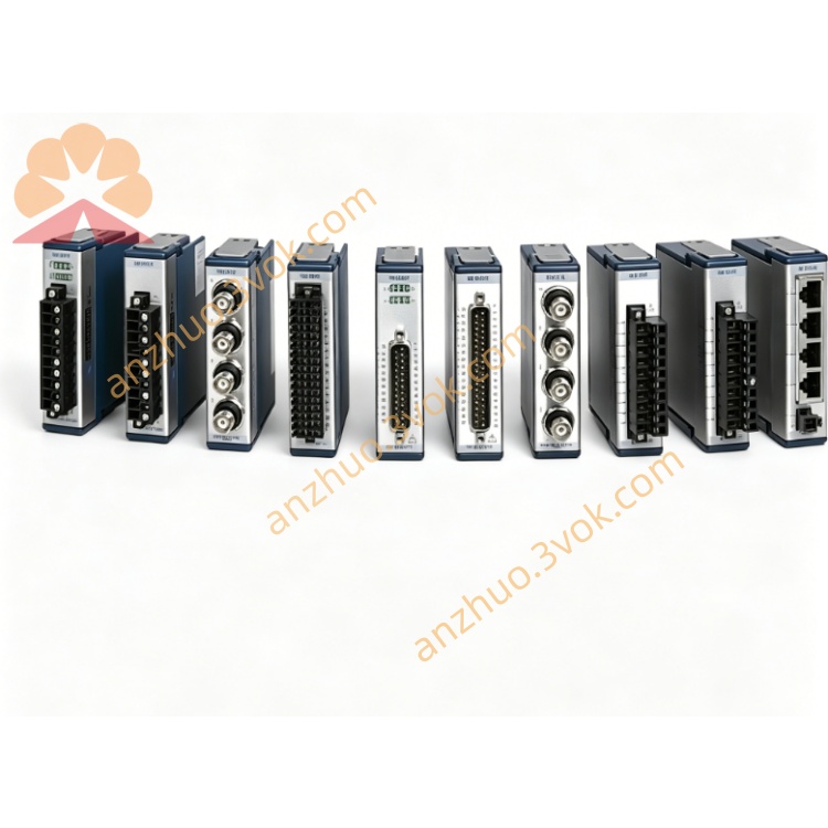
NI SCXI-100 (776990-01 / 182788C-01) 100-Pin Shielded DAQ Terminal Block
Description
I. Product Introduction
The NI SCB-100 is a 100-pin shielded signal junction box launched by National Instruments. It is specifically designed for data acquisition, digital I/O, and counter modules with 100-pin interfaces. The device converts high-density connectors into conventional screw terminals, facilitating on-site wiring and signal connection. The body integrates a shielding structure and a cold junction compensation circuit for thermocouple, balancing signal anti-interference capability and temperature measurement accuracy. It is a commonly used front-end signal transfer accessory in testing and measurement, and industrial data acquisition systems.
II. Model Interpretation
SCB represents the shielded junction box series, which is the abbreviation of Signal Conditioning Box. 100 indicates that the device is equipped with 100-pin standard interfaces and corresponding 100-channel screw terminals, distinguishing it from other junction box models with different channel quantities. This product has corresponding official part numbers, such as 776990-01 and 182788C-01. The current upgraded version of this series is SCB-100A.
III. Technical Parameters
The input end of the device uses 0.050-inch spacing 100-pin shielded D-type female connectors, and the output end is 100 independent screw terminals, including one vacant terminal. The applicable wire gauge range is 30 to 16AWG, and the standard tightening torque of the wiring screws is 0.5 to 0.6 newton-meters. It has a built-in cold junction compensation temperature sensor, with a temperature measurement accuracy of ±0.5 degrees Celsius and a temperature drift coefficient of 10 mV per degree Celsius. The working power supply is 5 volts DC, with a voltage fluctuation range of ±5%, and the typical working current of the entire machine is 10 milliamperes. The signal circuit has a maximum withstand voltage of 30 volts AC and 60 volts DC, which is only suitable for low-voltage signal scenarios. The entire machine supports desktop placement and rack installation. The working temperature range is 0 degrees Celsius to 55 degrees Celsius, the storage temperature range is -55 degrees Celsius to 125 degrees Celsius, the working environment humidity is 5% to 90% without condensation, and the product complies with RoHS environmental standards.
IV. Interface and Communication Configuration
One side of the device is a 100-pin shielded D-type interface, used to directly connect various 100-pin interface DAQ modules, digital I/O modules, and counter modules provided by NI. All screw terminals are arranged on the front of the body, used for external connection of sensors, thermocouples, relays, and external signal lines. The body is equipped with a function toggle switch, which can manually switch the activation and deactivation of functions such as cold junction compensation and status indicator lights. The entire machine is a pure hardware transfer device, requiring no additional driver programs. Signals are physically connected directly, and a complete shielding link can be achieved with shielded cables to enhance communication and transmission stability.
V. Core Functions
It realizes interface form conversion, converting the high-density 100-pin connectors at the device end into screw terminals that are convenient for manual wiring, significantly simplifying on-site wiring, line maintenance, and signal debugging work. The all-metal shielding shell combined with shielded interfaces effectively suppresses external electromagnetic interference, improving the transmission quality of weak signals. An integrated cold junction compensation module is included. When using a thermocouple for temperature collection, it can automatically complete cold junction temperature compensation, reducing measurement errors. A function toggle switch is provided, allowing for flexible activation or deactivation of functions such as cold junction compensation, power indicator lights, etc., to adapt to different measurement requirements for digital signals, analog signals, temperature signals, etc. The device comes with cable fixing clips to prevent the connection cables from being pulled off by external forces and ensure connection reliability.
VI. Application Scenarios
It is widely used in the industrial automation field to complete the wiring transfer of on-site sensors, relays, actuators, etc., and switch quantities and analog quantities of equipment. In automated testing equipment and production line functional testing systems, as the front-end wiring unit of the DAQ module, it realizes the centralized connection and distribution of multiple signals. It is applicable to various temperature collection scenarios and can be combined with thermocouples to complete multi-point temperature monitoring of equipment, chambers, and materials. It is also used in laboratory data collection, university research experiments, etc., providing a convenient and reliable signal conversion solution for various NI acquisition modules.
VII. Usage and Maintenance Instructions Instruction Manual
Before connecting, ensure that both the rear acquisition module and the junction box are in a power-off state. Connect one end of the matching shielded cable to the acquisition module, and lock the other end onto the 100-pin interface of the SCB-100 and secure the clip. Remove the insulation layer of the wire and insert it into the corresponding screw terminal. Tighten the screws according to the standard torque to avoid false connections or excessive wire compression that may damage the core. When using a thermocouple for temperature measurement, keep the cold junction compensation function of the equipment enabled. In digital signal transmission scenarios, the corresponding function can be turned off by using the code switch. The voltage of the connected line must not exceed the rated withstand voltage value. Do not connect to high-voltage or strong current circuits. After completing the connection, check the line layout to avoid excessive bending or squeezing of the cables.
Maintenance Instructions
Regularly use a dry soft cloth to wipe the surface of the equipment and the connection terminals, remove the accumulated dust to prevent dust accumulation from causing poor contact. Periodically inspect all connection terminals, connectors, and cables to check for any looseness, oxidation, or damage to the cable outer skin. Address any abnormalities promptly. Maintain a dry and ventilated environment for the equipment, away from strong electromagnetic radiation sources, high-temperature heat sources, and corrosive gases. When the equipment is to be stored for a long time, disconnect all external lines and power supply, and store the equipment in a cool and dry place. Do not plug in or unplug interface cables or loosen connection terminals while the equipment is powered on to prevent abnormal signals or hardware damage.
Get a Quote