
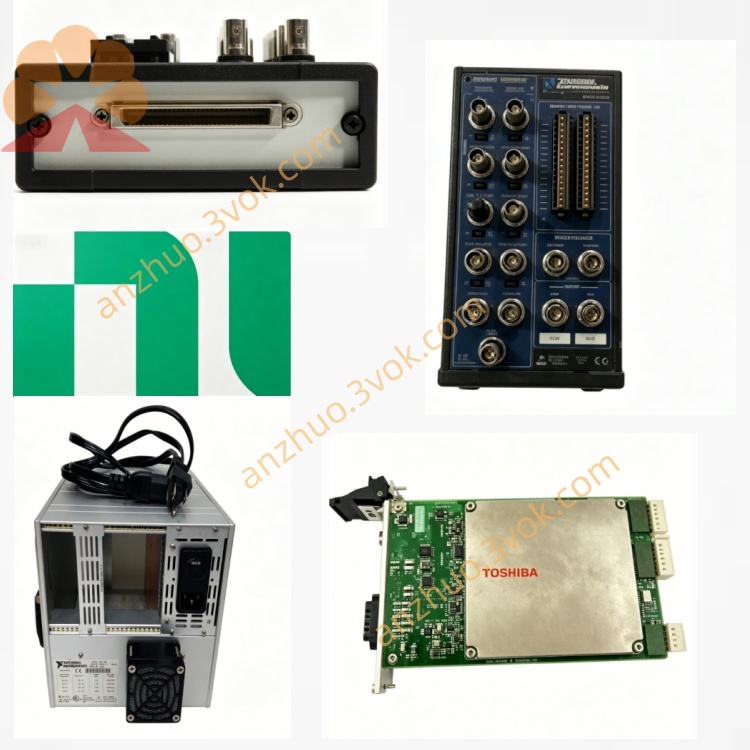
NI PXIe-1085-781813-01 18-Slot PXIe Express Chassis
Description
I. Product Overview
The NI PXIe-1085-781813-01 is a 18-slot, third-generation PXI Express high-performance hybrid chassis built on the PCIe Gen3 bus architecture, offering high data transfer bandwidth, excellent thermal management, and precise timing synchronization. Designed in standard 3U rack-mount form factor, it supports mixed insertion of PXI and PXIe modules and integrates comprehensive system monitoring with multi-chassis daisy-chaining capabilities. It serves as a mainstream chassis solution for large-scale, high-speed automated testing, measurement, and signal analysis systems. The 781813-01 variant represents the standard bandwidth configuration of this model.
II. Model Description
NI stands for National Instruments, the U.S.-based brand. "PXIe" denotes the PXI high-speed bus standard based on PCI Express technology. "1085" identifies the chassis product series, corresponding to an 18-slot, 3U hybrid chassis. "781813-01" is the complete part number; the suffix "01" indicates the standard bandwidth configuration, distinguishing it from higher-bandwidth variants within the same series.
III. Technical Specifications
The chassis features a total of 18 slots, including one system slot, one dedicated timing/synchronization slot, and 16 general-purpose hybrid peripheral slots. The backplane employs a fully mixed design, compatible with PXI, PXIe, CompactPCI, and CompactPCI Express modules. Total system bandwidth reaches 12 GB/s, with up to 4 GB/s of dedicated unidirectional bandwidth per slot. Power input supports AC 100V to 240V at frequencies of 50 Hz to 60 Hz. The chassis has a rated total power consumption of 925W, with a maximum allowable power draw of 38.25W per slot. Equipped with intelligent variable-speed fans, it operates at a minimum noise level of 51 dBA under normal conditions, ensuring effective heat dissipation for long-term operation of high-power modules. The chassis includes an internal 10 MHz reference clock with ±25 ppm accuracy and jitter below 5 ps, along with a 100 MHz synchronized clock, standard PXI trigger bus, star trigger, and differential star trigger functions. Physically, it adopts a standard 3U rack-mount structure and weighs 18.28 kg. Operating temperature range is 0°C to 55°C, storage temperature ranges from -40°C to 70°C, operating humidity is 10% to 90% (non-condensing), and maximum operational altitude is 2,000 meters.
IV. Interfaces and Communication Configuration
The front panel includes a main power switch and status indicator LEDs for power, system operation, faults, and fan status. The rear panel provides a rich set of external interfaces: a Gigabit Ethernet port supporting 10/100/1000 Mbps, enabling remote monitoring of chassis parameters such as voltage, temperature, and fan speed. Reserved MXI-Express and PCIe interfaces allow for multi-chassis daisy-chaining and expansion. Two SMA ports are provided for input and output of external 10 MHz reference clocks and trigger signals. An AC power input interface with overload protection is included, along with a remote power control interface that enables external signal-based device power-on/off and standby control. All slot interconnects—bus, clock, and trigger lines—are implemented via the internal backplane, ensuring reliable and stable signal transmission through hardware-level integrity.
V. Core Features
Supports full-slot hybrid compatibility, allowing flexible combination of PXI and PXIe modules across 16 peripheral slots without requiring additional hardware configuration, providing high flexibility in system setup. Based on third-generation PCIe technology, it delivers high-bandwidth data transfer, meeting demanding requirements for high-speed data acquisition, RF testing, and parallel multi-channel testing applications involving large data volumes. Equipped with a low-jitter clock and multi-type trigger buses, it enables precise timing synchronization among modules within a chassis and across multiple chassis, ensuring consistent test results. It features comprehensive intelligent monitoring capabilities, allowing remote access to device operating parameters via Ethernet and timely alerts for abnormal conditions. With high-power supply and an intelligent variable-speed cooling system, it supports various high-power consumption test modules, guaranteeing long-term continuous and stable operation. The system supports cascading expansion of multiple chassis, enabling scalable growth in test channels and equipment count, ideal for large-scale test system configurations.
VI. Application Scenarios
Suitable for high-speed digital testing, mixed-signal testing, and RF parameter measurement in semiconductor manufacturing lines. In aerospace and defense applications, it is used for research, development, and verification testing of radar systems, communication equipment, navigation systems, and electronic warfare devices. In automotive electronics, it supports multi-channel, high-concurrency testing tasks such as autonomous driving systems, vehicle networks, and battery management systems. It is also applicable in industrial automation for large-scale data acquisition on production lines, real-time monitoring of field equipment status, and distributed control. Additionally, it is widely used in scientific research laboratories for precision physical measurements, high-frequency signal analysis, and complex simulation experiments.
VII. Operation and Maintenance Instructions User Instructions
The device must be installed within a standard industrial rack, ensuring sufficient front and rear ventilation space during installation to prevent obstruction of airflow. Before wiring, verify that the input AC voltage matches the equipment specifications, then connect the power cable. All modules must be inserted into their respective slots only when the entire system is powered off. The system slot should be connected to the controller or interconnect card; the timing slot is reserved exclusively for synchronization-specific modules and must not accommodate general-purpose peripheral modules. After module installation, tighten the securing screws. Depending on application requirements, connect external clock and trigger signal lines to the rear SMA interfaces. For multi-chassis cascading, use dedicated cables to link PCIe or MXI-Express interfaces. After powering on, use NI MAX software to detect the chassis and all modules, configure network parameters, clock sources, trigger routing, and chassis topology, and install the corresponding version of PXI platform service programs and NI-VISA drivers. In high-temperature operating environments, adjust fan operation modes to prioritize effective heat dissipation.
Maintenance Instructions
Regularly clean the air intake and exhaust grilles and the exterior surface of the chassis with a dry soft cloth to prevent dust accumulation that could block airflow and impair cooling. Periodically inspect power cables, network cables, SMA signal cables, and all connectors for looseness, oxidation, or damage, and address any issues promptly. Maintain a dry, low-dust environment for the equipment, keeping it away from strong electromagnetic interference sources. If the device fails to be recognized, systematically check module installation, wiring connections, drivers, and network configuration. For transmission anomalies or synchronization failures, focus on troubleshooting clock lines, trigger lines, and backplane links. When operating temperatures are excessively high, inspect for blocked airflow paths and ensure fans are functioning properly. Never hot-swap modules, signal cables, or power lines while the device is powered on to avoid hardware damage. When the equipment is not in use for extended periods, disconnect the power supply and store it in a dry, well-ventilated area.
Get a Quote