TAC-311DG
Description
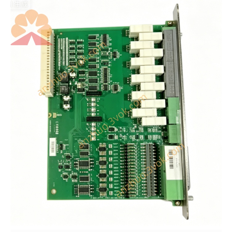
1. Product Overview
2. Main Features
Single-Function AC Current Measurement: Isolated, linear conversion of AC current to DC analogue signal.
High Accuracy: Class 0.5 compliance per IEC 688 for reliable measurements across operating temperatures.
Galvanic Isolation: Transformer-based isolation between input and output for safety and noise immunity.
Wide Input Range: 1.0–7.25 A AC direct input; compatible with standard 5 A CT secondary circuits.
Configurable DC Output: Standard 4–20 mA or 0–10 V DC analogue output (factory or user-configured).
Robust Overload Capability: Withstands 2× continuous, 10× for 10 s, and 40× for 1 s nominal current.
DIN Rail Mounting: Standard 35 mm DIN rail housing for simple cabinet integration.
LED Status Indicator: Front-panel red LED for calibration/configuration fault diagnostics.
Wide Operating Temperature: -10°C to +55°C for harsh industrial and marine environments.
Low Power Consumption: Optimised for minimal auxiliary power draw.
3. Technical Specifications
3.1 Input (AC Current)
Measuring Range: 1.0–7.25 A AC (direct)
Nominal Current (In): 5 A AC (standard CT secondary)
Burden: 1.2 VA max. at 5 A
Frequency Range: 45–65 Hz (50/60 Hz systems)
Overload:
Continuous: 2 × In
10 seconds: 10 × In
1 second: 40 × In
3.2 Output (DC Analogue)
Standard Ranges: 4–20 mA (default), 0–20 mA, 0–10 V DC
Accuracy: Class 0.5 (±0.5% of full scale)
Linearity: ±0.1% of full scale
Response Time: ≤200 ms (95% of final value)
Load Capacity:
Current Output: ≤500 Ω (4–20 mA)
Voltage Output: ≥10 kΩ (0–10 V)
3.3 Auxiliary Supply
AC Supply: 110/230/440 V AC ±20%, 45–65 Hz (max. 2.5 VA)
DC Supply: 24/48/110 V DC ±25% (max. 2 W)
3.4 Environmental Conditions
Operating Temperature: -10°C to +55°C
Storage Temperature: -40°C to +85°C
Relative Humidity: 5–95% RH, non-condensing
Vibration: 5–150 Hz, 0.1 mm amplitude (IEC 60068-2-6)
Protection Class: IP40 (housing), IP20 (terminals)
3.5 Mechanical Parameters
Mounting: 35 mm standard DIN rail
Dimensions (W×H×D): 45 × 75 × 110 mm
Housing: Flame-retardant engineering plastic (UL94 V-0)
Weight: ~600 g
Terminals: Screw-type, max. 4.0 mm² (single-stranded) / 2.5 mm² (multi-stranded)
4. Application Scope
Generator Current Monitoring: Isolated AC current measurement for diesel/gas generator sets.
Marine Switchboards: Current monitoring in vessel power distribution systems (SOLAS-compliant).
Industrial Motor Control: Overload and load current monitoring for AC motors.
Power Plant Monitoring: Current data acquisition for SCADA and data logging systems.
Renewable Energy Systems: Grid-tied inverter and wind turbine current measurement.
Panel Builders: Standardised current sensing for control and protection panels.
5. Installation and Wiring
5.1 Installation Requirements
Mount the unit vertically on a 35 mm DIN rail inside a control cabinet.
Maintain ≥10 mm clearance around the unit for ventilation and heat dissipation.
Install away from high-voltage cables, contactors, and frequency converters to minimise EMI.
Use anti-static precautions during installation to avoid component damage.
Do not install in corrosive, dusty, or condensing environments.
5.2 Wiring Rules
Perform all wiring with the auxiliary supply and measurement circuits de-energised.
Only qualified electrical personnel should install or maintain the transducer.
Input Wiring (AC Current):
Use 1.5–2.5 mm² shielded copper wire for CT secondary connections.
Never open CT secondary circuits during operation—risk of lethal high voltage.
Output Wiring (DC Analogue):
Use twisted pair (0.8–1.5 mm²) for 4–20 mA / 0–10 V signals.
Separate signal cables from power cables by ≥20 cm to reduce interference.
Auxiliary Supply Wiring:
Use 1.0–1.5 mm² copper wire for AC/DC power connections.
Tighten terminal screws to 0.6–0.8 Nm to prevent loose connections and overheating.
5.3 Terminal Definition
Auxiliary Supply:
AC: L (Line), N (Neutral)
DC: + (Positive), – (Negative)
AC Current Input: I+ (CT Secondary +), I– (CT Secondary –)
DC Analogue Output:
Current: OUT+ (4–20 mA +), OUT– (4–20 mA –)
Voltage: V+ (0–10 V +), V– (0–10 V –)
PE: Protective Earth (housing ground)
5.4 Wiring Notes
Connect the PE terminal securely to the cabinet ground for safety and EMC compliance.
CT secondary circuits must be closed at all times when the primary is energised.
Do not apply AC current exceeding 7.25 A continuously to the input terminals.
Ensure the output load resistance is within the specified range for accurate operation.
After wiring, double-check all connections for polarity and tightness before energising.
6. Operation and Configuration
6.1 LED Status Indicator
Off: Normal operation (no faults).
Slow Flash (1 Hz): Configuration error (invalid settings).
Fast Flash (5 Hz): Calibration data corrupted (contact DEIF support).
6.2 Factory Configuration
Input: 0–5 A AC (CT secondary)
Output: 4–20 mA DC (0 A = 4 mA, 5 A = 20 mA)
Auxiliary Supply: 230 V AC (50/60 Hz)
6.3 User Configuration (Optional)
Remove the front panel (use a screwdriver to release clips).
Connect the PC interface cable to the configuration port.
Launch the DEIF configuration software, detect the unit, and set:
Input range (1–7.25 A AC)
Output type (4–20 mA, 0–20 mA, 0–10 V)
Scaling and offset parameters
Save settings to non-volatile memory and reinstall the front panel.
6.4 Normal Operation
7. Safety Precautions
High voltage may be present on CT secondary circuits—always de-energise before wiring.
Never open CT secondary circuits during operation—risk of lethal high voltage.
Do not disassemble the unit without authorisation; voids warranty and risks electric shock.
Do not operate beyond specified input current, supply voltage, or temperature limits.
Keep the unit away from water, moisture, and corrosive substances.
In marine applications, comply with SOLAS requirements for electrical installations.
8. Maintenance
Monthly: Check terminal tightness, wire insulation, and LED status.
Quarterly: Clean dust from the housing with a dry soft cloth; do not use liquid cleaners.
Annually: Verify measurement accuracy using a calibrated current source and multimeter.
As Needed: Update configuration via DEIF PC software if application requirements change.
Replacement: If the unit fails or is damaged, replace it with a new TAC-311DG and reload configuration.
9. Troubleshooting
LED Fast Flash (5 Hz): Calibration data corrupted; contact DEIF support.
LED Slow Flash (1 Hz): Invalid configuration; restore factory settings or reconfigure.
No Output: Auxiliary supply missing, wiring error, or internal fuse blown.
Inaccurate Output: CT ratio mismatch, input overload, or incorrect scaling.
Unstable Output: EMI interference, loose connections, or excessive input ripple.
Overheating: Loose terminals, excessive ambient temperature, or overloaded input.
10. Warranty and Disclaimer
Model: TAC-311DG AC Current Single-Function Transducer.
Warranty Period: 24 months from delivery date (normal installation and use).
Warranty Exclusions: Damage from wrong wiring, overvoltage, lightning, water ingress, unauthorised disassembly, or operation beyond environmental specifications.
Modifications: Manufacturer reserves the right to update product specifications and this manual without prior notice.
Liability: Manufacturer shall not be liable for indirect, incidental, or consequential losses arising from improper installation or use.
Get a Quote