GPU/2/GS
Description
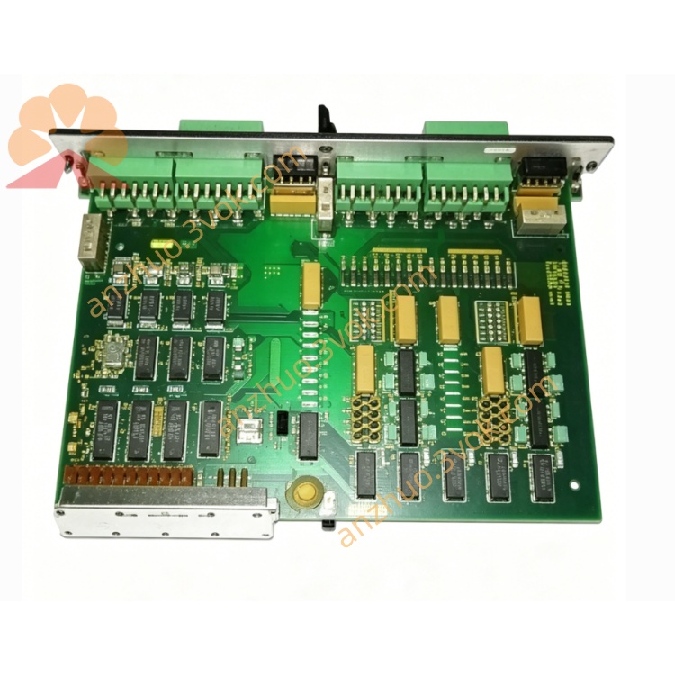
1. Product Overview
2. Main Features
Integrated multi-protection functions for generator voltage, frequency, current and power
Precise numerical setting of protection parameters, adjustable threshold and delay time
LED indicator for working status and fault type, clear at a glance
Fault latch function, keep fault status until manual reset
Remote alarm relay output, convenient for upper system monitoring
Industrial grade design, suitable for marine and harsh industrial environment
Built-in power surge, reverse polarity and EMC anti-interference circuit
Simple DIN rail mounting, easy wiring and commissioning
Low power consumption, stable long-term operation, maintenance-free
3. Technical Specifications
3.1 Power Supply
3.2 Measurement Input
3.3 Protection Functions
Over voltage protection: Threshold and time delay adjustable
Under voltage protection: Threshold and time delay adjustable
Over frequency protection: Adjustable trip point and delay
Under frequency protection: Adjustable trip point and delay
Over current protection: Inverse time / definite time optional
Reverse power protection: Prevent reverse power feeding to grid
Unbalanced voltage and phase sequence detection
Mains decoupling and generator islanding protection
3.4 Relay Output
3.5 Communication (Optional)
3.6 Environmental Conditions
3.7 Mechanical
4. Application Scope
Diesel / gas generator set comprehensive protection and monitoring
Marine generator switchboard protection and interlock control
Industrial factory standby generator automatic decoupling protection
Power distribution system mains-generator switching protection
Off-grid power station islanding and reverse power protection
Renewable energy distributed power generation grid-connected protection
5. Installation and Wiring
5.1 Installation Requirements
Install vertically on standard 35mm DIN rail inside control cabinet.
Reserve more than 20mm ventilation space around the unit for heat dissipation.
Keep away from frequency converters, large contactors and high-power interference equipment.
Take anti-static measures before installation to avoid damage to internal circuit.
Do not install in corrosive, dusty, dripping and condensing environment.
5.2 Wiring Rules
All wiring must be carried out under complete power-off condition, operated by qualified electrical personnel.
Voltage and current input wiring use 1.5~2.5mm² copper wire.
Current transformer input wiring must not be open-circuited under any operation.
Control power and signal lines shall be separated from high-power lines.
Terminal torque shall be controlled at 0.8~1.0 Nm to prevent loose contact and overheating.
5.3 Terminal Definition
Power terminals: +24V, 0V, PE earth
Voltage input: L1, L2, L3, N
Current input: CT1, CT2, CT3
Relay output: Alarm, Trip, Common
Communication: RS485 A, B
5.4 Wiring Notes
PE terminal must be reliably connected to cabinet ground for EMC and safety.
CT circuit must be connected firmly; never open CT terminals when powered on.
Do not apply overvoltage beyond the rated range to voltage input terminals.
Relay trip output shall be matched with breaker coil rated capacity.
6. Operation and Parameter Setting
6.1 Indicator Description
6.2 Parameter Configuration
After power on, enter parameter setting mode via onboard button or upper computer software.
Set rated voltage, rated frequency and CT ratio according to generator nameplate.
Configure each protection threshold and action delay time as required.
Set protection action mode: alarm only or alarm + trip.
Save parameters and exit setting mode; the unit enters normal monitoring state.
6.3 Normal Operation
7. Safety Precautions
High voltage exists on voltage and CT input terminals; wiring and maintenance must be done in power-off state.
It is strictly forbidden to disassemble the unit without authorization, otherwise the warranty will be invalid and electric shock risk may occur.
Prohibit operating beyond specified voltage, temperature and vibration limits.
Never open CT secondary circuit during operation, otherwise high dangerous voltage will be induced.
After protection tripping, must eliminate fault manually and reset before re-close.
8. Maintenance
Inspect terminal tightness and wire aging every 6 months.
Clean surface dust with dry soft cloth regularly.
Verify protection threshold and trip function annually.
Check relay contact ablation and communication connection status periodically.
9. Troubleshooting
No power indicator: 24VDC abnormal, reverse connection or internal fuse blown.
No protection action when parameter abnormal: Wrong parameter setting or wiring error.
False alarm / false trip: Parameter threshold too sensitive or external interference.
Communication failure: Wrong address, baud rate mismatch or RS485 A/B reversed.
Fault cannot be reset: Fault not eliminated or latch circuit abnormal.
10. Warranty and Disclaimer
Model: GPU/2/GS Generator Protection & Supervisory Unit
Warranty period: 24 months from delivery date under normal installation and use.
Warranty excludes damage caused by wrong wiring, overvoltage, lightning, water ingress, unauthorized disassembly and over-limit operation.
The manufacturer reserves the right to modify specifications and manual content without prior notice.
The manufacturer shall not be liable for indirect losses caused by improper installation and use.
Get a Quote