PCM4.4
Description
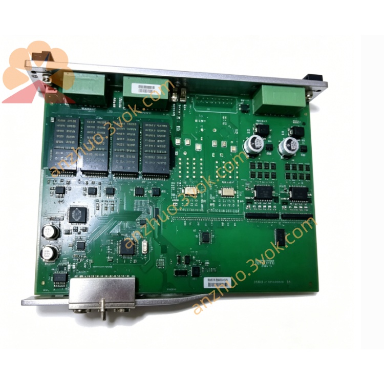
1. Product Overview
2. Main Features
Modular & Flexible I/O: Configurable digital/analog I/O channels to adapt to diverse field signals.
Multi-Protocol Support: PROFIBUS, CANopen, Modbus RTU/TCP, and Ethernet IP for seamless integration with PLCs and SCADA.
Industrial Grade Reliability: Wide-temperature (-25°C to +70°C) design, EMC protection, and vibration resistance for harsh environments.
Real-Time Processing: High-speed data acquisition and logic execution ensure precise control and fast response.
Remote Monitoring & Configuration: Supports remote parameter setup, fault diagnosis, and firmware updates via communication ports.
Compact DIN Rail Mount: Standard 35mm DIN rail installation saves cabinet space and simplifies wiring.
User-Friendly Software: Configuration tool for easy programming, logic editing, and data logging.
Fault Diagnosis & Protection: Built-in overvoltage, overcurrent, and reverse polarity protection; LED indicators for status and fault alerts.
3. Technical Specifications
3.1 Power Supply
Rated Voltage: 24 VDC
Operating Range: 18–30 VDC
Power Consumption: ≤ 12 W
Isolation: 2000 VAC between power and I/O circuits
3.2 Digital Inputs (DI)
Number of Channels: 8 (expandable)
Signal Type: 24 VDC level / dry contact
Low Level: ≤ 8 VDC; High Level: ≥ 16 VDC
Response Time: ≤ 5 ms
Isolation: Opto-isolated, 500 VAC per channel
3.3 Digital Outputs (DO)
Number of Channels: 8 (expandable)
Output Type: Relay (NO/COM/NC) or transistor (PNP/NPN)
Relay Rating: 250 VAC 5 A / 30 VDC 5 A
Transistor Rating: 24 VDC 0.5 A
Mechanical Life: ≥ 1,000,000 operations
3.4 Analog Inputs (AI)
Number of Channels: 4 (expandable)
Signal Type: 4–20 mA / 0–10 VDC
Resolution: 12-bit
Accuracy: ±0.1% FS
Sampling Rate: 100 Hz per channel
3.5 Analog Outputs (AO)
Number of Channels: 2 (expandable)
Signal Type: 4–20 mA / 0–10 VDC
Resolution: 12-bit
Accuracy: ±0.2% FS
Load Capacity: ≤ 500 Ω (current) / ≥ 1 kΩ (voltage)
3.6 Communication Interfaces
Fieldbus: PROFIBUS DP, CANopen, Modbus RTU
Ethernet: Modbus TCP, Ethernet IP (optional)
Serial: RS485 (Modbus RTU), RS232 (optional)
Baud Rate: 9.6 kbps – 1 Mbps (adjustable)
3.7 Environmental Conditions
Operating Temperature: -25°C to +70°C
Storage Temperature: -40°C to +85°C
Relative Humidity: 5–95% RH, non-condensing
Vibration: 5–150 Hz, 0.1 mm amplitude (industrial standard)
Protection Class: IP20 (front panel and terminals)
3.8 Mechanical Parameters
Mounting: Standard 35 mm DIN rail
Housing: Flame-retardant engineering plastic
Dimensions (W×H×D): 120 mm × 80 mm × 45 mm
Weight: ~ 350 g
4. Application Scope
Industrial Automation: Production line I/O expansion, logic control, and signal conversion.
Power Generation: Diesel/gas genset monitoring, protection, and control.
Marine Systems: Engine room automation, alarm interlock, and power management.
Process Control: Water treatment, chemical, and pharmaceutical plant data acquisition.
Building Automation: HVAC, lighting, and access control system integration.
Renewable Energy: Solar/wind power station peripheral signal control and grid connection.
5. Installation and Wiring
5.1 Installation Requirements
Mount vertically on a standard 35 mm DIN rail inside a control cabinet.
Maintain ≥ 20 mm clearance around the controller for heat dissipation.
Install away from frequency converters, large contactors, and high-power electromagnetic devices to minimize interference.
Use anti-static precautions during installation to avoid damage to internal components.
Do not install in corrosive, dusty, dripping, or condensing environments.
5.2 Wiring Rules
Perform all wiring with the power off; only qualified electrical personnel should install or maintain the unit.
Power wiring: 1.5–2.5 mm² copper wire; signal wiring: 1.0–1.5 mm² twisted pair.
Separate signal cables from high-voltage power cables to prevent electromagnetic interference.
Tighten terminal screws to 0.8–1.0 Nm to avoid loose connections and overheating.
Use shielded cable for long-distance signals; ground the shield at one end only.
5.3 Terminal Definition
Power: +24 VDC, 0 VDC, PE (protective earth).
Digital Inputs: DI1–DI8, COM (common).
Digital Outputs: DO1–DO8 (NO/COM/NC).
Analog Inputs: AI1–AI4 (4–20 mA / 0–10 VDC).
Analog Outputs: AO1–AO2 (4–20 mA / 0–10 VDC).
Communication: PROFIBUS (A/B), CANopen (H/L), RS485 (A/B), Ethernet (TCP/IP).
5.4 Wiring Notes
Connect the PE terminal securely to the cabinet ground for safety and EMC protection.
Do not apply voltage exceeding the rated range to input channels.
For inductive loads on relay outputs, use surge absorbers to protect contacts.
Avoid short-circuiting power terminals, which may cause permanent damage.
After wiring, double-check all connections to prevent miswiring or reverse polarity.
6. Operation and Configuration
6.1 Indicator Description
PWR: Steady on = power normal; Off = no power or fault.
RUN: Flashing = normal operation; Steady on/off = fault.
COM: Flashing = communication active; Off = no communication.
DI1–DI8: On = input active; Off = input inactive.
DO1–DO8: On = output active; Off = output inactive.
6.2 Configuration Steps
Connect the controller to a PC via USB or Ethernet.
Install the PCM4.4 configuration software (compatible with Windows 10/11).
Launch the software and detect the controller; set communication parameters (baud rate, address, protocol).
Configure I/O channels: set DI/DO types, AI/AO ranges, and logic functions.
Edit control logic (e.g., interlocks, timers, counters) using the software’s graphical or text-based editor.
Download the configuration to the controller; save the project file for future use.
Test I/O channels and communication to verify correct operation.
6.3 Normal Operation
7. Safety Precautions
High voltage may be present on I/O and communication terminals; always work with the power off.
Do not disassemble the controller; unauthorized disassembly voids the warranty and may cause electric shock.
Do not operate beyond the specified voltage, temperature, or vibration limits.
Avoid short-circuiting output contacts to prevent contact ablation and circuit damage.
After a fault, eliminate the cause before resetting and restarting the controller.
Keep the controller away from water, moisture, and corrosive substances.
8. Maintenance
Monthly: Check terminal tightness, wire condition, and LED status.
Quarterly: Clean dust from the surface with a dry soft cloth; do not use liquid cleaners.
Annually: Verify I/O accuracy, communication integrity, and relay contact condition.
As Needed: Update firmware via the configuration software to add features or fix bugs.
Replacement: If the controller fails or is damaged, replace it with a new unit and reload the configuration.
9. Troubleshooting
PWR Off: No 24 VDC power, reverse wiring, or internal fuse blown.
RUN Steady On/Off: Self-test failure, program error, or hardware fault.
COM Off: Incorrect communication settings, cable fault, or network error.
DI No Response: Wrong wiring, signal source failure, or input channel damage.
DO No Action: Logic error, load short circuit, or relay contact failure.
AI/AO Inaccurate: Calibration drift, wiring error, or signal interference.
False Tripping: Electrical interference, parameter misconfiguration, or ground loop.
10. Warranty and Disclaimer
Model: PCM4.4 Distributed I/O & Fieldbus Controller.
Warranty Period: 24 months from the date of delivery, under normal installation and use.
Warranty Exclusions: Damage from wrong wiring, overvoltage, lightning, water ingress, unauthorized disassembly, or operation beyond environmental specifications.
Modifications: The manufacturer reserves the right to update product specifications and this manual without prior notice.
Liability: The manufacturer shall not be liable for any indirect, incidental, or consequential losses arising from improper installation or use.
Get a Quote