1207000006C
Description
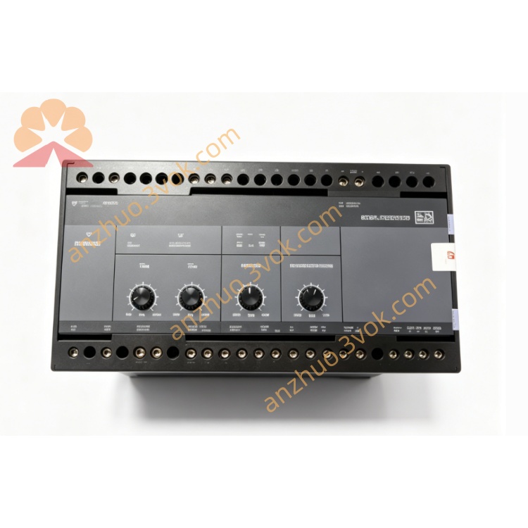
1. Product Overview
2. Main Features
Industrial grade wide temperature design, suitable for harsh industrial and marine working environment
Complete galvanic isolation between power supply, input and output circuits
Support active 24VDC level input and passive dry contact input signal
High reliability relay output contact, with large load driving capacity
Built-in reverse connection, overvoltage, overcurrent and lightning surge protection
Low power consumption design, long service life, maintenance-free operation
Standard 35mm DIN rail mounting, simple installation and convenient wiring
On-board working status indicator and channel status indicator for real-time operation diagnosis
Strong electromagnetic anti-interference ability, adapt to complex industrial field interference environment
3. Technical Specifications
3.1 Power Supply
3.2 Digital Input
3.3 Relay Output
3.4 Environmental Parameters
3.5 Mechanical Parameters
4. Application Scope
Diesel and gas generator set auxiliary signal acquisition and logic control
Marine engine room automation monitoring, alarm interlock control system
Industrial production line equipment logic interlock and signal expansion
Power distribution cabinet switching signal collection and automatic control
New energy wind and solar power station peripheral signal control
PLC peripheral remote I/O expansion and industrial signal conversion
5. Installation and Wiring Instructions
5.1 Installation Requirements
The module shall be installed vertically on standard 35mm DIN rail inside the control cabinet.
Keep at least 20mm ventilation clearance around the module to ensure heat dissipation.
Install away from frequency converters, large contactors and high-power electromagnetic equipment to reduce interference.
Take anti-static protection measures before installation to avoid static damage to internal electronic components.
Do not install in environments with corrosive gas, heavy dust, water dripping and condensation.
5.2 General Wiring Rules
All wiring operations must be performed under power-off condition; only qualified electrical personnel are allowed to install and maintain.
Power supply wiring adopts 1.5~2.5mm² copper wire; signal wiring adopts 1.0~1.5mm² twisted pair wire.
All signal lines shall be routed separately from high-voltage power lines to avoid electromagnetic coupling interference.
Terminal screws shall be tightened with standard torque 0.8~1.0Nm to prevent poor contact and heating.
Shielded cable is recommended for long-distance signal transmission, and the shielding layer shall be grounded at single end only.
5.3 Terminal Definition
Power terminals: 24VDC positive, 24VDC negative, protective earth PE
Digital input terminals: Each channel signal input and public common terminal
Relay output terminals: Each group of relay NO, COM, NC contact terminals
5.4 Wiring Notes
The PE protective earth terminal must be reliably connected to cabinet ground for safety protection and anti-interference.
Do not apply overvoltage exceeding the rated range to input channels.
Relay output is forbidden to exceed rated voltage and current; inductive load must be equipped with surge absorption device.
It is strictly prohibited to short-circuit the power input terminal, otherwise the internal circuit will be permanently damaged.
After wiring, check all circuits carefully to avoid wrong connection and reverse connection.
6. Operation and Working Principle
6.1 Indicator Description
6.2 Working Principle
6.3 Normal Operation State
7. Safety Precautions
There is electric shock hazard inside the circuit. All installation, wiring and maintenance must be operated in complete power-off state.
Unauthorized disassembly of the module shell is prohibited, which will void the warranty and cause electrical safety risks.
Do not use power supply and signal voltage beyond the specified rated range.
It is not allowed to use the module in ultra-high temperature, ultra-low temperature and strong vibration environment beyond the specification limit.
Avoid short-circuiting relay output contacts to prevent ablation of contacts and burnout of internal circuits.
Residual charge remains inside the module after power off; do not touch the terminals immediately.
8. Regular Maintenance
Inspect terminal wiring regularly to check for looseness, oxidation and discoloration.
Clean surface dust with dry soft cloth periodically; do not use liquid corrosive detergent.
Observe indicator status during daily operation to judge working condition.
Retighten all wiring terminals every 12 months, and test each input and output channel one by one.
Check the working stability of the module regularly, and replace it in time if there is misoperation or response delay.
9. Troubleshooting
Power indicator not on: Abnormal 24VDC power supply, reverse wiring or internal fuse damage.
Run indicator abnormal: Internal program error, circuit damage or parameter abnormality.
Digital input no response: Wrong wiring, signal source failure or input channel burnout.
Relay output no action: Internal logic error, load short circuit or relay contact damage.
Channel indicator abnormal: Line interference, terminal poor contact or internal circuit aging.
10. Warranty and Disclaimer
Product Part Number: 1207000006C Industrial Control Module
Warranty period: 24 months from the delivery date under normal installation and use conditions.
The warranty does not cover damage caused by wrong wiring, overvoltage, lightning strike, water ingress, manual disassembly and operation beyond environmental specifications.
The manufacturer reserves the right to update product specifications and manual content without prior notice.
The manufacturer shall not be liable for any indirect economic loss caused by improper installation and operation.
Get a Quote