
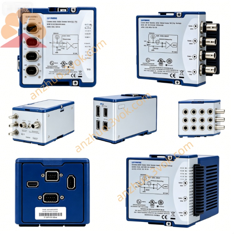
NI PXIe-2569 100CH SPST Latching Relay Switch Module
Description
Model Nomenclature
PXIe: PXI Express high‑speed modular instrumentation bus
25: NI switch/relay product series
69: 100‑channel SPST latching relay module, 100 V, 1 A, 20 MHz bandwidth
Technical Specifications
Form factor: 3U, 1‑slot PXIe (hybrid/peripheral slot compatible)
Relay topology: 100 independent SPST (NO) relays; software‑configurable as 50 DPST relays
Relay type: Latching armature (Form A), gold‑plated contacts
Number of channels: 100
Bandwidth: DC to 20 MHz
Maximum switching voltage: 100 VDC / 100 VAC (channel‑to‑channel/ground)
Maximum switching current: 1 A per channelNI
Maximum switching power: 60 W DC / 125 VA AC per channel
Minimum switch load: 20 mV or 10 mA
Actuation time: Typical 1 ms
Relay life: >10⁶ operations (rated conditions)
Scan rate: 145 cycles/s
Scan list depth: 32,000 steps (deterministic scanning)NI
Operating temperature: 0 °C to 55 °C; storage: −20 °C to 70 °C
Power consumption: 5 W @ 12 V, 2 W @ 3.3 V (PXIe)
Dimensions: 21.6 × 2.0 × 13.0 cm; weight: ~550 g
Interface and Communication Configuration
Front‑panel I/O: 100×screw terminals (2‑wire per channel) for signal connections
Bus: PXIe Gen1, plug‑and‑play (compatible with PXI hybrid slots)
Triggering: PXI trigger lines 0–7; input trigger min. pulse width 150 ns; output trigger pulse width 1–62 μs for multi‑module synchronization
Software support: NI‑MAX for configuration; LabVIEW, LabWindows/CVI, C++ APIs with NI‑SWITCH driverNI
Compatibility: Windows OS, 3U PXI/PXIe chassis
Core Features
High‑density 100‑channel design: Delivers the highest relay count per slot for compact, scalable test systemsNI.
Software‑configurable topology: Reconfigures between 100 SPST or 50 DPST modes without hardware changes.
Latching relay technology: Maintains state without continuous power, reducing power consumption and heatNI.
Deterministic scanning: 32,000‑step scan list enables precise, repeatable automated test sequencesNI.
Medium‑power handling: Supports up to 100 V / 1 A for switching power circuits, sensors, and low‑voltage devices.
Overvoltage protection: Withstands 800 V impulse voltage and suppresses transients from inductive loads.
Application Scenarios
Automated test equipment (ATE): High‑channel‑count signal routing for functional and parametric testing of PCBs, connectors, and electronic assemblies.
Fault insertion testing: Simulating open/short circuits, voltage faults, and signal disruptions in embedded systems and automotive electronics.
Power supply and load switching: Routing DC/AC power to DUTs, sensors, and actuators in industrial test benches.
Semiconductor test: Low‑frequency signal switching for discrete components, ICs, and power devices.
General‑purpose relay control: High‑density, cost‑effective relay control for research, validation, and manufacturing test systemsNI.
Get a Quote