
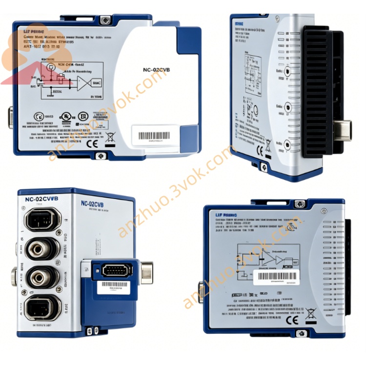
NI PXI-8336 Fiber-Optic MXI-4 PXI System Interface Module
Description
Model Nomenclature
PXI: PCI eXtensions for Instrumentation, adhering to modular instrumentation bus standards.
8336: MXI-4 series identifier; the suffix 6 denotes fiber-optic transmission (vs. 1 for copper in PXI-8331).
MXI-4: Fourth-generation multi-system extension interface, a dedicated protocol for cross-chassis PCI bridging.
Technical Specifications
Form Factor: 3U, single-slot PXI chassis occupancy.
Bus Interface: Standard PCI backplane connection; compliant with PXI Rev 2.1 and PCI Rev 2.2.
Protocol: MXI-4; serial data rate 1.5 Gbit/s.
Bandwidth: Peak 132 MB/s; sustained 78 MB/s.
Topologies: Daisy-chain and star; up to 254 cascaded links (BIOS-dependent).
Fiber-Optic Cables: Multi-mode; lengths 10 m, 30 m, 200 m.
Power: 5 V DC from PXI backplane; typical 1.4 A at 5 V, <0.34 A at 3.3 V.
Environment: Operating temperature 0–55 °C; storage -20–70 °C; humidity 10–90% non-condensing; altitude up to 2,000 m.
Weight: ~0.25 kg (0.55 lb).
Interface and Communication Configuration
Front Panel Port: Dedicated MXI-4 fiber-optic connector for multi-mode cable connection.
PCI-to-PCI Bridge: Hardware-based transparent bus bridging for seamless data transmission.
Signal Forwarding: Transfers PXI trigger and RTSI synchronization signals across chassis for multi-device sync.
Error Handling: MXI-4 protocol integrates CRC checking and automatic retransmission for reliability.
LED Indicators: Real-time status for power, link, and data activity.
Software: Requires NI-PXI drivers; compatible with LabVIEW Real-Time and NI-VISA.
Core Features
Transparent Bus Extension: Remote PXI modules are enumerated and controlled as local hardware, no code changes needed.
Fiber-Optic Advantages: Up to 200 m transmission, complete electrical isolation, superior EMI immunity for industrial environments.
High Reliability: CRC and auto-retransmission ensure stable communication in noisy settings.
System Scalability: Connect PCs to PXI chassis or multiple PXI chassis for large distributed test systems.
Legacy Compatibility: Works with older PXI/VXI devices, facilitating system upgrades.
Precision Synchronization: Cross-chassis trigger/RTSI forwarding for accurate multi-module data acquisition.
Application Scenarios
Distributed Automated Test: Control-room hosts managing production-line PXI chassis in aerospace, semiconductor, and automotive electronics.
Harsh Industrial Environments: Power plants, rail transit, and manufacturing floors with strong electromagnetic interference.
Long-Distance Monitoring: Structural health monitoring, remote equipment testing, and geographically dispersed test systems.
Legacy System Upgrades: Seamless integration of traditional PXI/VXI equipment with modern host platforms.
Multi-Chassis Synchronization: Large-scale test platforms requiring synchronous data acquisition across multiple PXI chassis.
Usage and Maintenance Instructions
Installation & Configuration
Insert into a 3U PXI chassis slot (preferably near the system controller).
Connect multi-mode fiber-optic cables between MXI-4 ports on PXI-8336 modules (no hot-swap during power-on).
Power on devices in sequence; system auto-detects links and remote hardware.
Enable MXI-4 functions in BIOS and configure PCI memory windows.
Install NI-PXI drivers for trigger, interrupt, and advanced functionality support.
Daily Maintenance
Inspect fiber-optic cables, connectors, and ports regularly for wear, damage, or looseness.
Operate within rated temperature/humidity; keep chassis clean and dry.
For EOL units, stock spare modules/cables to avoid downtime.
Monitor front-panel LEDs and use NI diagnostic tools for fault localization.
Store idle equipment in dry conditions; perform periodic power-on tests to prevent moisture damage.
Safety & Disposal
Avoid hot-swapping cables/modules when powered on.
Do not exceed environmental ratings to prevent hardware damage.
Dispose of in accordance with local regulations for EOL electronic equipment.
Get a Quote