
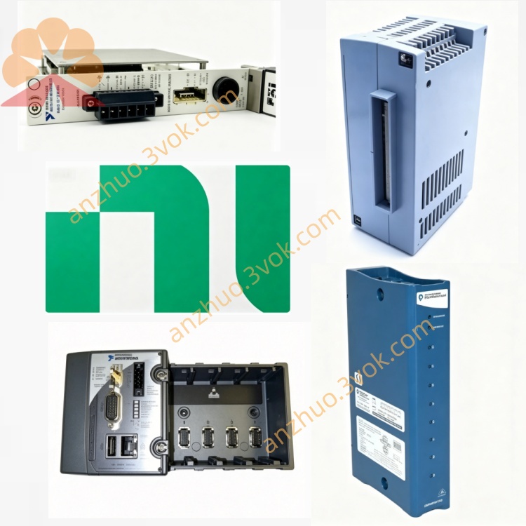
NI PXI-8330 MXI-3 Copper PXI Remote Extension Interface Module
Description
Model Nomenclature
PXI: PCI eXtensions for Instrumentation, compliant with the PXI modular instrumentation bus standard.
8330: Denotes the MXI‑3 3rd‑generation multi‑system extension interface; the trailing 0 indicates the copper cable version (8335 is the fiber‑optic version).
Part Number: 777945‑01.
Technical Specifications
General
Form Factor: 3U PXI, single‑slot width.
Host Interface: PCI bus (PXI backplane).
Protocol: MXI‑3 (hardware PCI‑to‑PCI bridge).
Peak Bandwidth: 132 MB/s.
Sustained Bandwidth: 84 MB/s.
Serial Data Rate: 1.5 Gbit/s.
Max Number of Links: 254 (BIOS‑dependent).
Topology: Daisy‑chain or star configuration supported.
Cable & Distance
Copper Cable: 2 m, 5 m, 10 m options.
Fiber‑Optic Cable: Up to 200 m (multi‑mode).
Electrical & Environmental
Power Requirement: +5 VDC, 1.5 A (supplied via PXI backplane).
Dimensions: 10.0 × 16.0 cm (3.9 × 6.3 in).
Operating Temperature: 0 °C to 50 °C.
Storage Temperature: −20 °C to 70 °C.
Operating Humidity: 10% to 90%, non‑condensing.
Interface & Communication Configuration
MXI‑3 Connector: High‑speed serial port on the front panel for copper/fiber cable connection.
PCI‑to‑PCI Bridge: Hardware‑level bridge that transparently extends the PCI bus, requiring no additional drivers for basic operation.
Trigger & Interrupt Routing: Passes PXI trigger bus and RTSI synchronization signals remotely for multi‑chassis synchronous acquisition.
LED Indicators: Front‑panel LEDs for power, link status, and activity monitoring.
Core Features
- Transparent PCI Bus ExtensionThe MXI‑3 acts as a hardware PCI‑to‑PCI bridge, enabling the host to directly enumerate, read/write, and control remote PXI modules as if they were local to the host PC, requiring no programming for basic operation.
- Long‑Distance Extension & Electrical IsolationFiber‑optic cables support distances up to 200 m and provide electrical isolation, making the module suitable for high‑EMI industrial environments.
- High Bandwidth & Low LatencyDelivers 132 MB/s peak bandwidth and 84 MB/s sustained throughput, meeting requirements for high‑speed data acquisition, image transmission, and synchronized testing.
- Multi‑System InterconnectionSupports PC ↔ PXI, PXI ↔ PXI, and PXI ↔ VXI connections, enabling the construction of large‑scale distributed test systems.
- Legacy System CompatibilityWorks with Windows 2000/XP/7 and legacy LabVIEW RT versions, allowing integration with existing legacy test infrastructures.
Application Scenarios
Distributed ATE Test Systems: Host PC in a control room connected to PXI chassis on production lines for remote test control.
Mixed‑Bus Systems: Integration of PXI, VXI, and desktop PCs into a unified test architecture.
High‑EMI Industrial Environments: Power, rail transit, and industrial field applications using fiber isolation for noise immunity.
Long‑Term Structural Health Monitoring: Bridges, tunnels, and wind farms requiring remote, long‑distance data acquisition.
Usage & Maintenance Instructions
Installation
Install the module into any 3U PXI chassis (e.g., PXI‑1042, PXI‑1045), preferably in a slot near the system controller.
Connect one end of the MXI‑3 copper/fiber cable to the PXI‑8330 and the other end to a PCI‑8330/8335 module in the host PC or another PXI chassis.
Power on the chassis; the system automatically enumerates the MXI‑3 link and remote PCI devices.
Configuration
Enable MXI‑3 support in the system BIOS and configure memory windows for the PCI‑to‑PCI bridge.
Install NI‑PXI drivers for full functionality (e.g., trigger routing, interrupt handling).
Maintenance
Inspect cables and connectors periodically for damage or loose connections.
Keep the module and chassis in a clean, dry environment within specified temperature/humidity ranges.
For obsolete hardware, maintain spare modules and cables to avoid system downtime.
If issues occur, check LED status indicators and use NI diagnostic tools to troubleshoot link or communication errors.
Get a Quote