TCM-2
Description
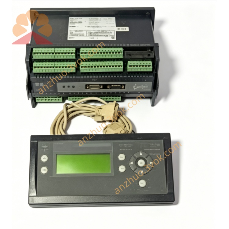
1. Product Overview
2. Key Features
Robust Industrial Design: Built for extreme conditions (wind turbine nacelle environments).
Advanced RPM-Based Control: Unique double cut-in ramp reduces grid impact and protects the drivetrain.
High-Voltage Compatibility: Direct 3-phase 690 VAC voltage measurement.
High Precision: Class 0.5 accuracy for power, voltage, and current measurements.
Flexible Current Input: 1 A / 5 A CT selectable secondary.
Comprehensive Communication: EtherCAT, CAN, SSI, TCP/IP, RS-422/485 interfaces.
Extended Operating Temperature: –40 °C to +70 °C.
High Shock & Vibration Resistance: Designed for 50 g shock and 2.1 g vibration.
Open Software Platform: Linux-based, supports C/C++ and CODESYS (IEC 61131-3).
Fail-Safe Operation: Fault-tolerant file system and safe firmware updates.
3. Technical Specifications
3.1 General
| Parameter | Specification |
|---|---|
| Model | TCM-2 |
| Manufacturer | DEIF A/S |
| Type | Thyristor Control Module / Soft Starter |
| Application | Asynchronous generator grid connection (wind turbines) |
| Measurement Accuracy | Class 0.5 (±0.5% FS) |
| Operating System | Linux (fault-tolerant) |
| Software | C/C++, CODESYS (IEC 61131-3) |
3.2 Input Ratings
| Parameter | Specification |
|---|---|
| Voltage Input (Vn) | 3 × 690 VAC (L-L), direct |
| Current Input (In) | 1 A or 5 A (CT secondary, selectable) |
| Frequency | 50 / 60 Hz (45–65 Hz range) |
3.3 Environmental & Mechanical
| Parameter | Specification |
|---|---|
| Operating Temperature | –40 °C to +70 °C (cold start capable) |
| Storage Temperature | –40 °C to +85 °C |
| Humidity | 97% RH (condensing, 55 °C) |
| Altitude | < 4,000 m |
| Vibration | 2.1 g (3.2–50 Hz); 1.0 g (13.2–100 Hz) |
| Shock | 50 g, 11 ms (half sine) |
| Bump | 25 g, 6 ms (half sine) |
| Protection Class | IP20 (terminals), IP40 (housing) |
| Dimensions (W×H×D) | 255 × 140 × 80 mm |
| Weight | Approx. 2.5 kg |
| Mounting | Panel mount (4 × M5 screws) |
3.4 Communication & I/O
| Interface | Type |
|---|---|
| EtherCAT | Fieldbus (real-time I/O) |
| CAN | CANopen / J1939 |
| SSI | Synchronous Serial Interface (encoder) |
| TCP/IP | Ethernet (Modbus TCP) |
| RS-422/485 | Serial (Modbus RTU) |
| Digital Inputs | 4 × 24 VDC |
| Digital Outputs | 2 × Relay (250 VAC, 5 A) |
3.5 Power Supply
| Parameter | Specification |
|---|---|
| Auxiliary Supply | 24 VDC ±20% |
| Power Consumption | ≤ 20 W |
4. Application Scope
Wind Turbines: Soft grid connection for doubly-fed or full-power converter asynchronous generators.
Industrial Generators: Standby/prime power asynchronous generator paralleling.
Marine Power Systems: Heavy-duty generator control for vessels and offshore platforms.
Grid Support: Reducing inrush current and grid voltage dip during generator start-up.
5. Installation & Wiring
5.1 Installation Requirements
Mounting: Install vertically on a rigid panel (4 × M5 screws).
Clearance: Allow ≥50 mm clearance on all sides for ventilation.
Environment: Avoid direct sunlight, dust, moisture, and corrosive gases.
ESD Protection: Discharge static before handling (PCB is ESD-sensitive).
5.2 Terminal Wiring
5.2.1 Power & Measurement Inputs
| Terminal | Description |
|---|---|
| L1/L2/L3 | 3-phase voltage input (up to 690 VAC) |
| CT1/CT2/CT3 | Current transformer inputs (1 A / 5 A) |
| +24V/GND | 24 VDC auxiliary power supply |
5.2.2 Communication Ports
| Port | Description |
|---|---|
| ETH | EtherCAT / TCP/IP (Ethernet) |
| CAN | CAN bus (CANopen) |
| SSI | Encoder input (speed feedback) |
| RS485 | Modbus RTU (serial) |
5.2.3 Digital I/O
| Terminal | Description |
|---|---|
| DI1–DI4 | Digital inputs (24 VDC) |
| DO1–DO2 | Relay outputs (250 VAC, 5 A) |
5.3 Wiring Notes
High Voltage: Only qualified electricians may install/service. Disconnect all power before wiring.
CT Wiring: Never open-circuit CT terminals (risk of lethal high voltage).
Cable Size: 2.5 mm² (power circuits); 1.5 mm² (control/communication).
Terminal Torque: Tighten to 1.2–1.5 Nm.
Shielding: Use shielded cable for communication; ground shield at both ends.
6. Operation & Configuration
6.1 Front Panel Indicators
PWR: Solid green = 24 VDC supply OK.
RUN: Flashing green (1 Hz) = normal operation.
FAULT: Solid red = system fault (overtemperature, overcurrent, communication error).
READY: Solid yellow = unit ready for generator cut-in.
6.2 Configuration Steps (DEIF PC Tool)
Connect: Use Ethernet cable to connect TCM-2 to PC.
Install: Download and install DEIF TCM-2 Configuration Tool (free from www.deif.com).
Connect to Device: Select TCM-2 from the device list.
Set Parameters:
Generator Data: Rated power, voltage, current, speed.
Cut-In Ramp: Configure RPM-based double ramp (rise time, slope, delay).
Protection Limits: Overvoltage, undervoltage, overcurrent, overtemperature.
Communication: Set EtherCAT/CAN/Modbus addresses and baud rates.
Write Config: Download settings to TCM-2.
Verify: Start generator; check READY LED and communication status.
6.3 Normal Operation
Generator Run-Up: TCM-2 monitors generator speed and voltage.
Cut-In Initiation: At predefined RPM, soft start sequence begins.
Double Ramp Control: Thyristors gradually increase voltage to grid, limiting inrush current.
Grid Synchronization: Smooth transition to full grid voltage; thyristors bypassed.
Fault Monitoring: TCM-2 continuously monitors for faults; triggers alarm/trip if detected.
7. Safety Precautions
High Voltage Hazard: The unit operates with up to 690 VAC. Only qualified electricians may install or service.
Lethal CT Voltage: Never open-circuit CT terminals.
Overload Protection: Do not exceed rated voltage/current limits.
Environmental Limits: Operate only within –40 °C to +70 °C.
No Unauthorised Modification: Do not open the enclosure; voids warranty.
Emergency Shutdown: Use external emergency stop button to disconnect power in case of fault.
8. Maintenance
8.1 Regular Maintenance (Every 12 Months)
Visual Inspection: Check for loose terminals, damaged wiring, or discolouration.
Cleaning: Remove dust from vents with compressed air (low pressure).
Terminal Tightness: Retorque to 1.2–1.5 Nm.
Communication Test: Verify all communication interfaces.
Protection Test: Simulate fault conditions to verify alarm/trip functionality.
Insulation Resistance: Measure ≥1 MΩ @ 500 VDC between power circuits and ground.
9. Troubleshooting
| Fault Phenomenon | Possible Cause | Solution |
|---|---|---|
| PWR LED Off | No 24 VDC supply / wrong polarity | Check wiring; verify supply voltage. |
| FAULT LED On | Overtemperature / Overcurrent / CT open | Check ambient temp; reduce load; check CT wiring. |
| READY LED Off | Generator speed/voltage out of range | Adjust generator excitation; check speed sensor. |
| No Grid Connection | Cut-in ramp misconfiguration | Verify ramp settings in PC tool. |
| Communication Loss | Wrong address / cable fault | Check wiring; verify communication parameters. |
10. Warranty & Disclaimer
Model: TCM-2 Thyristor Control Module.
Warranty Period: 24 months from delivery (normal installation/use per manual).
Warranty Exclusions: Misuse, overvoltage, lightning, water ingress, unauthorised modification, or CT open-circuit.
Specifications Subject to Change: Manufacturer reserves the right to update specifications without notice.
Get a Quote