
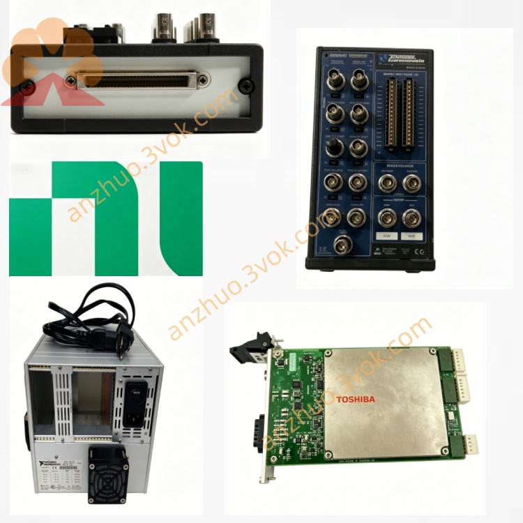
NI PXI‑2541 6.6GHz 50‑Ohm Solid‑State SP8T RF Switch Module
Description
Model Explanation
PXI: PXI bus platform
2541: Product serial number, representing an 8×12 RF matrix switch (350 MHz)
Alias: NI-2541, PXI-2541 (RF 8×12 matrix)
Function Positioning: 8 rows × 12 columns high-density RF matrix, reed relays, high isolation, cascading expansion NI
Technical Parameters
Topology Structure: 8×12 single-line matrix (96 cross points), non-blocking NI
Relay Type: Reed relay (Reed), magnetic retention
Frequency Range: DC to 350 MHz (–3 dB) NI
Characteristic Impedance: 50 Ω
Maximum Switching Voltage: 60 VDC
Maximum Switching Current: 500 mA/channel
Maximum Switching Power: 10 W (DC)
RF Power (350 MHz): Typical + 20 dBm
Insertion Loss: Typical < 2.1 dB (300 MHz)
Channel Isolation: Typical > 75 dB (300 MHz)
Return Loss: Typical > 18 dB (300 MHz)
Switching Time: Typical < 1 ms
Relay Lifespan: Typical 10⁸ times (resistive load)
I/O Connector: 20×MCX female (8 rows + 12 columns)
Size: 3U PXI single slot
Weight: Approximately 300 g
Operating Temperature: 0–55 °C
Interface and Communication Configuration
PXI Bus Interface: Standard 3U PXI backplane, power supply, trigger, clock, communication
Front-end I/O: 20 MCX female (R0–R7, C0–C11), including row expansion I/O (Row In/Out)
Adapter Cable: MCX-MCX direct connection; optional MCX to BNC/SMB/SMA
Control Software: Compatible with NI- SWITCH, MAX, LabVIEW, TestStand
Trigger Synchronization: 2 channels of PXI hardware trigger, nanosecond-level synchronization
Expansion Capability: Multi-module cascading (8×24, 8×36…), dedicated cascading cable NI
Core Function
8×12 Non-blocking RF Matrix: 96 cross points, any row/column can be simultaneously conductive, high test flexibility NI.
DC to 350 MHz wideband: Covers medium and low-frequency RF, analog and mixed signals NI.
High Isolation and Low Loss: > 75 dB isolation, < 2.1 dB insertion loss, ensuring signal integrity.
Magnetic Retaining Reed Relays: Low contact resistance, long lifespan (10⁸ times), low power consumption.
Hardware Trigger and Scanning: Nanosecond-level synchronization, high-speed sequence scanning, improving test throughput.
On-board Relay Counting: Real-time recording of switching times, predicting maintenance cycle. Applicable scenarios
Consumer electronics RF testing: Testing of low and medium frequency radio frequency functions such as Bluetooth, WiFi, NFC, and FM.
Semiconductor / chip testing: Parameter testing and aging screening of RF chips and mixed-signal ICs.
Communication module manufacturing: Calibration, functional verification, and multi-channel signal routing of RF modules.
ATE automated testing system: Reuse of instruments, multi-channel RF signal switching, cost reduction by NI.
Research and development laboratory: RF signal switching, instrument interconnection, signal distribution and routing.
User and maintenance instructions
Key usage points
Installation: Standard 3U PXI chassis single slot, lock the panel, ensure reliable contact of the backplane.
Configuration: NI-SWITCH/MAX set channel mapping, trigger parameters, scan sequence.
Connection: MCX connector should be inserted and removed gently; do not exceed pressure (60 VDC), current (500 mA), or power.
RF considerations: 50 Ω impedance matching; ensure good grounding, keep away from strong electromagnetic interference.
Environment: 0–55 °C, dust-proof, moisture-proof, condensation-proof; keep away from vibration sources.
Maintenance instructions
Regular inspection: Check the tightness of MCX connectors and for any looseness/oxidation every quarter; clean the surface dust.
Life management: Monitor the count of relays, evaluate replacement when approaching 10⁸ times; avoid long-term high power/high frequency switching.
Troubleshooting: First check the MCX connection and grounding for abnormal signals; use software to diagnose the relay status; take precautions against static electricity.
Storage: Power off when not in use, store in a dry, dust-proof environment, cover the connector with a dust cap to prevent moisture and oxidation.
Get a Quote