
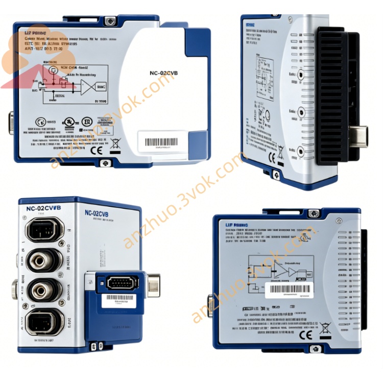
NI PXI‑2532 512‑Crosspoint Reed‑Relay Matrix Switch Module
Description
Model Explanation
PXI: PXI bus platform (modular instrument standard for testing and measurement)
2532: Product serial number, representing a 512 cross-point high-density matrix switch
Alias: PXI-2532, NI-2532, 778572-32 (part number)
Function Positioning: Reconfigurable matrix switch, supporting multiple topologies such as single-line and double-line, used for high-precision signal switching by NI
Technical Parameters
Cross-point Number: 512 (composed of 16 groups of 2×16 matrices) NI
Topology Configuration (Single Line): 4×128, 8×64, 16×32, dual 4×64, dual 8×32, dual 16×16, quad 4×32 NI
Topology Configuration (Double Line): 4×64, 8×32, 16×16, dual 4×32 NI
Relay Type: Reed (dry contact), rhodium contact NI
Maximum Switching Voltage: 300 Vrms (CAT II)
Maximum Switching Current: 0.5 A/channel, maximum switching power 10 W
Bandwidth: Single line ≥ 30 MHz, double line ≥ 25 MHz
Thermal Offset: < 1 μV (ultra-low thermoelectric potential)
Isolation Level: 150 V CAT II
Trigger Characteristics: PXI trigger line 0–7, minimum pulse width 150 ns; output trigger 1–62 μs, software selectable NI
Size: 3U PXI module (160 × 100 × 30 mm)
Weight: Approximately 0.8 kg
Status:停产; recommended replacement: PXIe-2532BNI
Interface and Communication Configuration
PXI Bus Interface: Standard 3U PXI backplane connector, providing power supply, trigger, clock and communication NI
Front-end I/O Connector: 2 × 160-pin Samtec BTE-EM series high-voltage connector NI
Terminal Block (optional): SCB-2586, etc., supports ribbon cable or screw terminal leads
Control Communication: PXI bus, compatible with NI- SWITCH, MAX configuration software NI
Trigger Synchronization: Hardware trigger input/output, supports synchronization with other instruments in the PXI system NI
Expansion Capability: Multiple modules can be cascaded through the terminal block to expand the matrix size NI Core function
High-density matrix switching: 512 cross points per slot, flexible configuration of multiple topologies, meeting the requirements of multi-channel signal routing for NI.
Ultra-low thermal offset: < 1 μV, suitable for low-level, high-precision measurements (such as thermocouple, sensor signals).
High-voltage isolation: 150 V CAT II isolation, allowing safe switching of mixed high-low voltage signals.
Hardware triggering and synchronization: nanosecond-level triggering, supporting high-speed scanning and multi-instrument synchronization, enhancing test throughput for NI.
Relay life monitoring: onboard relay counting, predicting maintenance cycles, reducing unexpected downtime for NI.
Reconfigurable topology: flexible switching of single-line / double-line matrices through software and terminal blocks, adapting to different testing requirements for NI. Applicable scenarios
Aerospace electronic automation testing: Multi-channel signal switching and fault injection.
Semiconductor wafer testing: High-density probe card signal routing.
Automotive ECU verification: Sensor and load signal simulation and switching.
Industrial sensor network monitoring: Multi-node round-trip collection and switching.
Precision instrument calibration: High-precision switching of low-level and weak signals.
User and Maintenance Instructions
Key Usage Points
Installation: Insert into the standard 3U PXI chassis slot, lock the panel after insertion, and ensure reliable contact of the backplane connector.
Configuration: Select the matrix topology through NI-SWITCH or MAX software, and define channel mapping and trigger parameters NI.
Cabling: Connect the 160-pin connector to the terminal block (such as SCB-2586), and then transfer it to the tested device; for high voltage / large current, connect according to specifications to avoid overload.
Operation Monitoring: Use the onboard relay counting function to regularly read the number of switching operations and evaluate the lifespan NI.
Environment: Operating temperature 0–50 °C. Avoid strong electromagnetic interference, dust, and condensation.
Maintenance Instructions
Regular Inspection: Check the connector tightness and whether the terminal block wiring is loose every quarter. Clean the surface dust.
Relay Lifespan Management: Typical lifespan of a bimetal relay: 10 V/100 mA approximately 10⁷ times; 20 V/500 mA approximately 5×10⁶ times; 100 V/10 mA approximately 5×10⁵ times. Replace the module in time when approaching the lifespan.
Troubleshooting: When the channel is not working or has poor contact, first check the wiring and terminal block, then diagnose the relay status through software; check the grounding and shielding when the thermal offset exceeds the limit.
Storage: When not in use for a long time, disconnect the power supply and store in a dry, dust-proof environment to avoid moisture and oxidation of the connector.
Get a Quote