
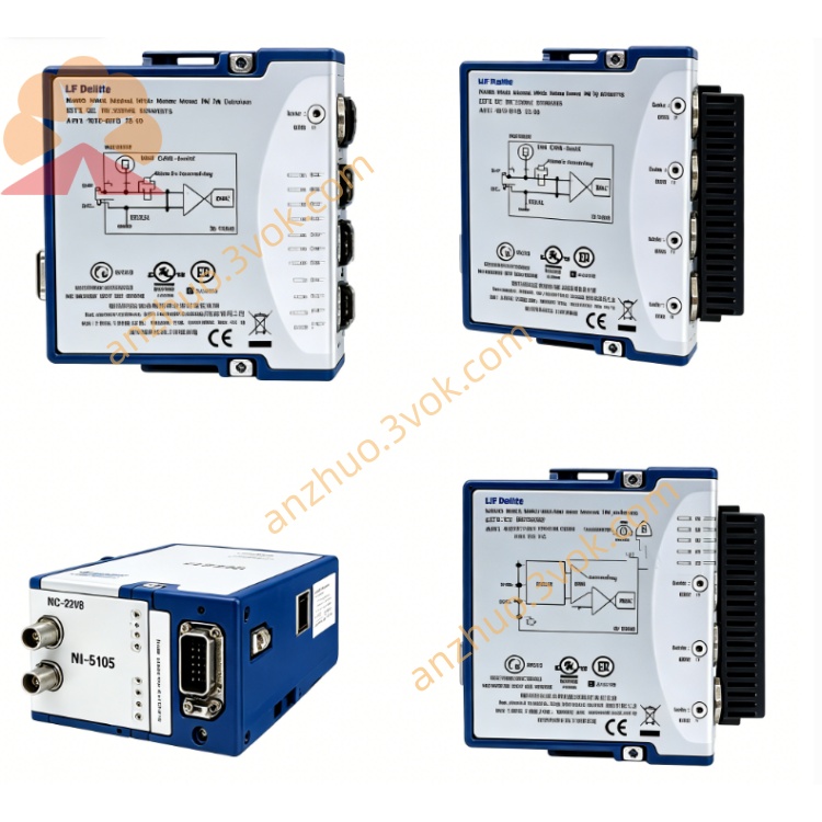
NI PXI‑2529 128‑Crosspoint Electromechanical‑Relay Matrix Module
Description
II. Model Interpretation
PXI: PCI eXtensions for Instrumentation, compatible with standard PXI and PXIe mixed slots.
2529: NI 2500 series switch module, representing 128 cross points, dual-line matrix, electromechanical latch relay specifications.
Part number: 778739-01, etc.
Product status: In stock.
III. Technical Parameters
1. Channels and Topology
Total cross points: 128.
Configuration topology: 8×16 dual-line, 4×32 dual-line, dual 4×16 dual-line.
Relay type: Electromechanical latch relay (holds state during power loss).
Contact material: Silver-palladium alloy plated gold, low contact resistance, corrosion-resistant.
2. Electrical Characteristics
Maximum switching voltage: 150 VDC/150 VAC (CAT I), capable of withstanding 800V surge.
Maximum switching current: 1 A/channel; maximum carrying current: 2 A/channel.
Maximum switching power: 30 W (DC), 37.5 VA (AC).
On-state resistance: Initial < 1 Ω; life termination ≥ 2 Ω.
Thermal electromotive force: < 9 μV, suitable for low-voltage precision measurement.
Minimum switching current: 10 μA.
Relay life: Typical 10^7 times under resistive load.
3. Dynamic Performance
Scan rate: 120 cycles/second.
Switching time: < 5 ms (typical).
4. Physical and Environmental
Form: 3U PXI single slot (21.6 cm×2.0 cm×13.0 cm).
Weight: Approximately 210 g.
Operating temperature: 0–55 ℃; storage: -20–70 ℃.
Humidity: 10%–90% RH (no condensation).
Power consumption: 6 W at 5V supply; 2.5 W at 3.3V supply.
IV. Interface and Communication Configuration
Bus interface: Standard PXI mixed bus, supports hot plugging, plug-and-play, compatible with PXI/PXIe chassis.
Signal interface: Front panel 100-pin HDI high-density male connector, suitable for dual-line topology wiring.
Trigger and synchronization: PXI trigger line (0–7), supports hardware triggering, multi-module synchronous scanning.
Software driver: Companion NI-SWITCH driver, compatible with LabVIEW, TestStand, LabWindows/CVI, supports C/C++/Python API and IVI standard driver.
V. Core Functions
High-density matrix routing: 128 cross points, supports 8×16/4×32 / dual 4×16 three topologies, realizes flexible connection between any channels.
Low thermal electromotive force precision measurement: < 9 μV thermal electromotive force, suitable for thermocouples, sensors, etc. for high-precision acquisition of low-voltage weak signals.
Latch relay low power consumption: Holds channel state during power loss, no need for continuous power supply, reduces system energy consumption.
Built-in relay count: Built-in action count, supports predictive maintenance, early detection of aging relays.
High-speed synchronous scanning: 120 cycles/second scanning rate, hardware triggering synchronization, improves multi-channel testing efficiency.
VI. Application Scenarios
Precise signal testing system: Multi-channel acquisition and calibration of low-voltage signals such as thermocouples, strain gauges, sensors.
Automated ATE equipment: High-density functional testing and signal routing of consumer electronics, semiconductors, circuit boards.
Power and load testing: Voltage/current/resistance inspection and aging test of multiple power supplies, DC-DC modules.
Industrial control and monitoring: Multi-channel signal switching and status monitoring of control cabinets, transmitters, actuators. Aerospace and Defense: High-precision instruments, signal distribution and verification testing for avionics equipment.
VII. Operating and Maintenance Instructions
1. Installation and Wiring
The module must be unplugged and re-plugged while the power is off. After inserting into the PXI/PXIe slot, tighten the fixing screws.
Connect the 100-pin HDI interface cables according to the topological specification. Do not exceed 150V or 1A. Only CAT I measurement circuits are allowed.
The chassis and the tested equipment should be reliably grounded to reduce electromagnetic interference and electrostatic damage.
2. Software Configuration
Install the NI-SWITCH driver. Identify the module through NI-MAX and configure the matrix topology.
Implement functions such as channel switching, automatic scanning, and synchronous measurement through LabVIEW or text-based programming.
3. Daily Maintenance
After a regular power outage, clean the panel and interfaces with a dust-free soft cloth to prevent dust and liquids from entering the ports.
Maintain the working environment at 0–55 ℃ without condensation. Avoid areas with strong electromagnetic interference.
Avoid connecting inductive loads. If connecting inductive devices, a surge protection circuit must be added.
When plugging or unplugging the module or wiring, wear an anti-static wrist strap to prevent static discharge from damaging the internal circuits.
Get a Quote