Description
1. Product Overview

2. Key Features
Dedicated Short‑Circuit Protection (I>>): Fast‑acting overcurrent protection for short‑circuit faultsDEIF.
Ultra‑Fast Response: <50 ms operating time (instantaneous, no intentional delay)DEIF.
Adjustable Trip Threshold: 100–400% of CT secondary rated current (1 A or 5 A)DEIF.
Single Set of Contacts: 1× relay output (NO/COM/NC) for trip/alarm signalingDEIF.
LED Status Indicators: POWER and SHORT CIRCUIT LEDs for immediate visual statusDEIF.
Wide Auxiliary Supply: 24 VDC ±20% or 110/230 VAC ±10% (optional).
DIN‑Rail Mount: Compact 35 mm DIN‑rail housing for standard cabinet installationDEIF.
Industrial & Marine Certified: CE, IEC 60945 (marine), UL 61010‑1.
Conformal Coating: Protected against humidity, dust, and corrosive environments.
3. Technical Specifications
3.1 Electrical Ratings
| Parameter | Specification |
|---|---|
| Model | RMC‑111D (Short‑circuit relay, I>>) |
| Manufacturer | DEIF A/S |
| Part Number | 4921240130 (standard) |
| CT Input | |
| – Rated Current | 1 A or 5 A (selectable via internal jumper)DEIF |
| – Input Burden | ≤0.5 VA |
| – Frequency | 50/60 Hz ±5% |
| Trip Characteristics | |
| – Short‑Circuit Threshold (I>>) | 100–400% In (adjustable via potentiometer)DEIF |
| – Response Time | <50 ms (instantaneous)DEIF |
| – Accuracy | ±5% of set value |
| Auxiliary Supply | |
| – DC | 24 VDC ±20% (18–30 VDC), ≤2 W |
| – AC (Optional) | 110/230 VAC ±10%, 50/60 Hz, ≤3 VA |
| – Fusing | 1 A slow‑blow (internal) |
| Relay Output | |
| – Contact Configuration | 1× NO/COM/NC (single set)DEIF |
| – Rating | 250 VAC / 8 A (resistive), 30 VDC / 8 A |
| – Mechanical Life | ≥100,000 operations |
3.2 Environmental & Mechanical
| Parameter | Specification |
|---|---|
| Operating Temperature | –20 °C to +60 °C (marine: –30 °C to +60 °C) |
| Storage Temperature | –40 °C to +85 °C |
| Humidity | 5–95% RH non‑condensing |
| Vibration | 2–13.2 Hz: ±0.7 mm; 13.2–100 Hz: ±0.5 g |
| Enclosure | IP20 (front/terminals); conformal coated PCB |
| Dimensions (W×H×D) | 75 × 105 × 55 mm (4TE)DEIF |
| Weight | Approx. 0.44 kg |
| Mounting | 35 mm DIN rail (horizontal/vertical)DEIF |
4. Application Scope
Generator Protection: Short‑circuit protection for small‑to‑medium synchronous generators (marine/industrial).
Motor Control: Instantaneous short‑circuit protection for AC motors (pumps, fans, compressors).
Transformer Feeders: Primary/secondary short‑circuit protection for distribution transformers.
Marine Switchboards: Shipboard power distribution systems (IEC 60945 certified).
Industrial Panels: Standalone short‑circuit protection in control panels and MCCs.
Retrofit Projects: Upgrade legacy protection systems with fast, reliable I>> protection.
Hybrid Power Systems: Short‑circuit isolation in solar/wind‑diesel hybrid plants.
5. Installation & Wiring
5.1 Installation Requirements
Mounting: Install on 35 mm DIN rail (horizontal preferred) in a ventilated cabinet; ≥25 mm clearance top/bottom.
Environment: Avoid direct sunlight, moisture, corrosive gases, and excessive vibration.
ESD Protection: Use anti‑static wristband when handling (static‑sensitive PCB).
Cable Separation: Separate CT input cables from auxiliary supply cables by ≥5 cm.
5.2 Terminal Wiring (Simplified)
| Terminal | Description | Wire Gauge |
|---|---|---|
| CT Input (1 A/5 A) | ||
| 1–2 | CT Secondary (L1/K1, L2/K2) | 2.5 mm² (twisted‑pair) |
| Auxiliary Supply | ||
| 3–4 | 24 VDC (+/−) or 110/230 VAC | 1.5 mm² |
| 5 | Chassis ground (PE) | 2.5 mm² |
| Relay Output | ||
| 6 | NO (Normally Open) | 1.5 mm² |
| 7 | COM (Common) | 1.5 mm² |
| 8 | NC (Normally Closed) | 1.5 mm² |
CT Polarity: Match CT phase polarities; never open CT secondary circuits with primary current flowing (lethal voltage).
Shielding: Use shielded twisted‑pair cable for CT inputs; ground shield at RMC‑111D end only.
Terminal Torque: Tighten terminals to 0.6–0.8 Nm to prevent loose connections and overheating.
Fusing: Protect auxiliary supply with 1 A slow‑blow fuse; CT inputs require no external fusing.
5.3 Jumper & Switch Settings
CT Ratio Selection: Internal jumper (J1) for 1 A or 5 A CT secondary (match system CTs).
No Communication: RMC‑111D is a standalone relay with no digital communication ports.
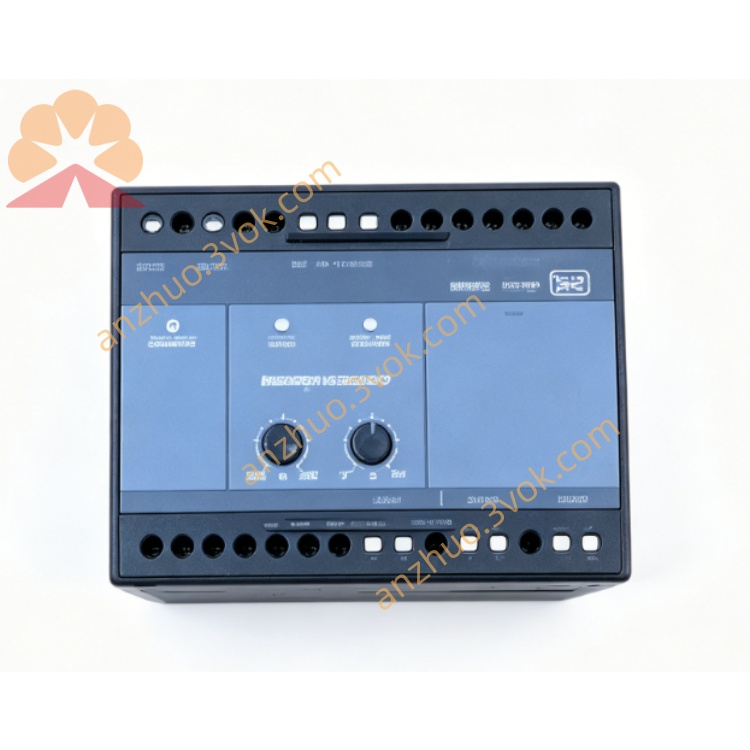
6. Front Panel & Operation
6.1 Front Panel Layout

LED Indicators (Left to Right)
POWER: On = Auxiliary supply OK.
SHORT CIRCUIT: On = Short‑circuit fault detected (relay tripped).
Adjustment Potentiometer
I>> ADJ: Rotate to set short‑circuit threshold (100–400% In)DEIF.
6.2 Startup & Configuration
Physical Installation: Mount RMC‑111D on DIN rail; connect CT inputs, auxiliary supply, and relay output wiring.
CT Ratio Setup: Set internal jumper J1 to 1 A or 5 A (match CT secondary rating).
Power On: Apply auxiliary supply; POWER LED illuminates (green).
Threshold Adjustment:
Calculate set point: I>> = (Desired Trip Current / CT Primary Current) × 100%.
Rotate I>> ADJ potentiometer to the calculated percentage (100–400% In).
Example: 500/5 A CT, trip at 2000 A → I>> = (2000 / 500) × 100% = 400%.
Relay Output Wiring: Connect NO/COM to trip circuit breaker or alarm annunciator.
6.3 Normal Operation
POWER LED: Solid green (auxiliary supply healthy).
SHORT CIRCUIT LED: Off (no fault).
Relay State: De‑energized (NO contact open, NC contact closed).
6.4 Fault Operation (Short Circuit)
SHORT CIRCUIT LED: Solid red (fault detected).
Relay State: Energized (NO contact closes, NC contact opens → trips breaker/alarm).
Reset: Remove fault current; relay resets automatically (LED off, relay de‑energized).
7. Safety Precautions
High Voltage Hazard: Only qualified electrical personnel may install/service. Disconnect all power sources (auxiliary + CT primary) before wiring.
CT Overvoltage Risk: Never open CT secondary circuits with primary current flowing (lethal voltage). Short CTs before connecting/disconnecting.
ESD Sensitivity: Static electricity can damage internal PCB. Use anti‑static wristband and grounded ESD mat.
Relay Load Ratings: Do not exceed 250 VAC/8 A per output; inductive loads require external surge suppression.
No Unauthorised Modification: Do not open the enclosure or modify internal circuits. Tampering voids warranty and may cause unsafe operation.
Environmental Limits: Do not operate outside –20 °C to +60 °C (standard) or –30 °C to +60 °C (marine).
8. Maintenance & Storage
8.1 Regular Maintenance (Every 12 Months)
Visual Inspection: Check for loose terminals, damaged wiring, corrosion, or overheating signs (discolouration).
Cleaning: Wipe front panel with dry lint‑free cloth; no liquid cleaners (avoid water ingress).
LED Check: Verify POWER/SHORT CIRCUIT LEDs operate correctly.
Terminal Tightness: Retorque all terminals to 0.6–0.8 Nm.
Functional Test: Inject secondary current above set threshold; verify SHORT CIRCUIT LED and relay operation.
Insulation Resistance: Measure between CT inputs and ground (≥1 MΩ at 500 VDC).
8.2 Storage Guidelines
Packaging: Store in original anti‑static packaging with desiccant.
Environment: 10–30 °C, 30–70% RH, dry, clean, and dust‑free.
Protection: Avoid direct sunlight, extreme temperatures, and mechanical shock/vibration.
Duration: Shelf life ≤5 years. Inspect for ESD damage and test basic functions before use if stored longer.
9. Troubleshooting
| Fault Phenomenon | Possible Cause | Solution |
|---|---|---|
| POWER LED Off | No auxiliary supply / blown internal fuse | Check DC/AC wiring; replace 1 A fuse. |
| SHORT CIRCUIT LED On (No Fault) | CT shorted / wiring error / threshold too low | Check CT connections; verify wiring; increase I>> setting. |
| No Trip on Short Circuit | Threshold too high / CT ratio mismatch / relay fault | Decrease I>> setting; correct J1 jumper; test/replace relay. |
| Relay Chatters | Loose wiring / unstable auxiliary supply | Retorque terminals; stabilize supply voltage. |
| CT Input Burnout | CT secondary open with primary current | Never open CT secondary; short CTs before wiring. |
10. Warranty & Disclaimer
Model: RMC‑111D Short‑Circuit Protection Relay.
Warranty Period: 24 months from delivery date (normal installation/use per manual).
Warranty Exclusions: Misuse, overvoltage, lightning, water ingress, unauthorised modification, improper maintenance, or CT/VT faults.
Specifications Subject to Change: Manufacturer reserves the right to update specifications without prior notice.
Liability Limitation: Manufacturer is not liable for indirect or consequential damages (e.g., downtime, lost revenue, equipment damage).
Documentation Version: 1.0 (2026); latest manual available at www.deif.com.
Get a Quote