Description
1. Product Overview
2. Key Features
All‑in‑One Control: Paralleling, synchronization, load sharing, and protection for gensets (single/multi‑unit, mains parallel).
3‑Phase Precision Measurement: 100–690 VAC, 1/5 A CT, 50/60 Hz; voltage/current/frequency/power/PF monitoring.
Automatic Synchronization: Frequency, phase, and voltage matching for seamless breaker closure.
Load Sharing: Droop/isochronous load sharing (active/reactive) for parallel gensets.
Comprehensive Protection (ANSI):
Over/under voltage (27/59)
Over/under frequency (81O/U)
Overload (37)
Reverse power (32)
Short‑circuit (50/51)
Earth fault (50N/51N)
Flexible I/O: 8×digital inputs, 6×relay outputs (250 VAC/8 A), 2×0–20 mA analog outputs.
Communication: RS‑232 (PC utility), RS‑485 (Modbus RTU, optional).
Display & Operation: 16×2 LCD with 6‑button keypad for local monitoring/configuration.
Certifications: CE, IEC 60945 (marine), UL 61010‑1.
DIN‑Rail Mount: Compact 8TE size for standard cabinet installation.
3. Technical Specifications
3.1 Electrical Ratings
| Parameter | Specification |
|---|---|
| Model | PPU‑2 (PPU/2/GS standard) |
| Manufacturer | DEIF A/S |
| Part Number | 4921240313 (standard)DEIF |
| AC Measurement Inputs | |
| – Voltage | 100–690 VAC (L1/L2/L3), <0.5 mA, 50/60 Hz |
| – Current | 1 A or 5 A CT secondary, <0.3 VA |
| – Accuracy | ±0.5% FS (V/I); ±0.1 Hz (frequency) |
| Auxiliary Supply | |
| – Voltage | 12/24 VDC ±20% (10–30 VDC) |
| – Power | ≤15 W (full load) |
| – Fusing | 1 A slow‑blow (internal) |
| Control I/O | |
| – Digital Inputs | 8× (24 VDC, sink/source) |
| – Relay Outputs | 6× (250 VAC/8 A resistive, NO/COM) |
| – Analog Outputs | 2× 0–20 mA (load sharing/voltage control) |
| Communication | |
| – RS‑232 | 9.6 kbps (PC utility, configuration) |
| – RS‑485 (Opt) | Modbus RTU, 19.2 kbps (multi‑drop) |
3.2 Environmental & Mechanical
| Parameter | Specification |
|---|---|
| Operating Temperature | –20 °C to +60 °C (marine: –30 °C to +60 °C) |
| Storage Temperature | –40 °C to +85 °C |
| Humidity | 5–95% RH non‑condensing |
| Vibration | 2–13.2 Hz: ±0.7 mm; 13.2–100 Hz: ±0.5 g (marine) |
| Enclosure | IP20 (front/terminals); conformal coated PCB |
| Dimensions (W×H×D) | 200 × 180 × 50 mm (8TE) |
| Weight | Approx. 1.0 kg |
| Mounting | 35 mm DIN rail (horizontal) |
4. Application Scope
Marine Gensets: Shipboard auxiliary generators (single/parallel), mains synchronization, and power management.
Industrial Standby Power: Small‑to‑medium gensets (hospitals, data centers, factories) with auto‑synchronization.
Offshore Platforms: Emergency/utility gensets (oil/gas platforms) with rugged marine certification.
Mills & Process Plants: Parallel gensets for continuous process power (load sharing & protection).
Retrofit Projects: Upgrade legacy DEIF PPU‑1 or non‑DEIF controllers to Multi‑Line 2 with minimal wiring.
Hybrid Power Systems: Genset control for solar/wind‑diesel hybrid plants (load following & synchronization).
5. Installation & Wiring
5.1 Installation Requirements
Mounting: Install on 35 mm DIN rail (horizontal) in a ventilated cabinet; ≥50 mm clearance top/bottom.
Environment: Avoid direct sunlight, moisture, corrosive gases, and excessive vibration.
ESD Protection: Use anti‑static wristband when handling (static‑sensitive PCB).
Cable Separation: Separate high‑voltage (AC measurement) and low‑voltage (DC/communication) cables by ≥10 cm.
5.2 Terminal Wiring (Simplified)
| Terminal Group | Description | Wire Gauge |
|---|---|---|
| Auxiliary Power | ||
| 1–2 | 24 VDC (+/−) | 1.5 mm² |
| 3 | Chassis ground (PE) | 2.5 mm² |
| AC Voltage Inputs (L1/L2/L3) | ||
| 4–6 | 100–690 VAC (line‑line) | 2.5 mm² |
| AC Current Inputs (CT1/CT2/CT3) | ||
| 7–9 | 1 A or 5 A CT secondary | 2.5 mm² |
| Digital Inputs (DI1–DI8) | ||
| 10–17 | 24 VDC (start/stop, breaker status, alarms) | 1.5 mm² |
| Relay Outputs (DO1–DO6) | ||
| 18–19 | DO1: NO/COM (breaker close) | 2.5 mm² |
| 20–21 | DO2: NO/COM (breaker open) | 2.5 mm² |
| 22–23 | DO3: NO/COM (alarm) | 1.5 mm² |
| 24–25 | DO4: NO/COM (trip) | 1.5 mm² |
| 26–27 | DO5: NO/COM (governor control) | 1.5 mm² |
| 28–29 | DO6: NO/COM (excitation control) | 1.5 mm² |
| Analog Outputs (AO1–AO2) | ||
| 30–31 | AO1: 0–20 mA (load sharing) | 1.0 mm² (shielded) |
| 32–33 | AO2: 0–20 mA (voltage control) | 1.0 mm² (shielded) |
| Communication | ||
| 34–35 | RS‑232 (TX/RX, PC utility) | 1.0 mm² |
| 36–37 | RS‑485 (A/B, Modbus RTU, opt) | 1.0 mm² (twisted‑pair) |
CT Polarity: Strictly match CT phase polarities; never open CT secondary circuits with primary current flowing.
Shielding: Use shielded cable for analog/communication lines; ground shield at PPU‑2 end only.
Terminal Torque: Tighten terminals to 0.8–1.0 Nm to prevent loose connections and overheating.
Fusing: Protect AC voltage inputs with 2 A slow‑blow fuses; relay outputs with 10 A max fuses (inductive loads).
5.3 Jumper & Switch Settings
Node Address: Rotary switch S1 (1–F, hex) for RS‑485 Modbus slave address.
RS‑485 Termination: Jumper X1 (120 Ω, enable at bus ends).
CT Ratio: Jumper X2 (1 A or 5 A, match CT secondary).
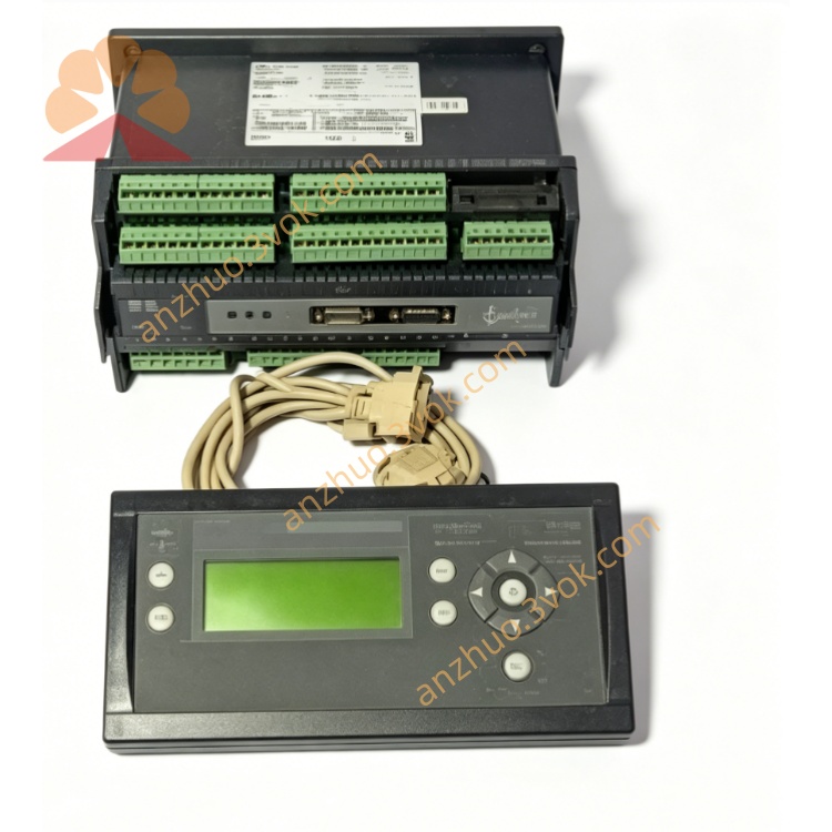
6. Front Panel & Operation
6.1 Front Panel Layout
LED Indicators (Left to Right)
POWER: On = 12/24 VDC supply OK.
RUN: Flashing = Normal operation; Solid = Fault/trip.
SYNC: Flashing = Synchronizing; Solid = Synchronized (breaker closed).
ALARM: On = Active alarm; Flashing = Unacknowledged alarm.
TRIP: On = Protection trip activated (breaker open).
LCD Display (16×2 characters):
Top row: Measured values (V, I, Hz, kW, kVAr).
Bottom row: Status, alarms, trip messages, and menu options.
Keypad (6 buttons):
▲/▼: Scroll menus/values.
◄/►: Move cursor/select fields.
ENTER: Confirm selection/save settings.
ESC: Exit menu/cancel changes.
6.2 Startup & Configuration
Physical Installation: Mount PPU‑2 on DIN rail; connect DC power, AC inputs, I/O, and communication wiring.
Switch/Jumper Setup: Set S1 node ID; X2 CT ratio; enable X1 termination (if RS‑485 used).
Power On: Apply 12/24 VDC; POWER LED on; RUN LED flashes; LCD shows startup screen (DEIF PPU‑2, firmware version).
AC Input Check: Verify balanced voltage/current; frequency = 50/60 Hz.
Basic Parameters (Menu 1000):
Nominal Voltage: 400/440/480 VAC (match system).
Nominal Frequency: 50 Hz or 60 Hz.
CT Ratio: 1 A or 5 A (match CT secondary).
PT Ratio: 1 (direct) or as per VT (if used).
Synchronization (Menu 2000):
Sync Mode: Auto (default) or Manual.
Frequency Window: ±0.5 Hz (adjustable).
Phase Window: ±10° (adjustable).
Voltage Window: ±5% Un (adjustable).
Protection (Menu 3000, Defaults):
Overvoltage: 115% Un, 2 s delay.
Undervoltage: 85% Un, 2 s delay.
Overfrequency: 105% Fn, 1 s delay.
Underfrequency: 95% Fn, 1 s delay.
Overload: 125% In, 10 s delay.
Reverse Power: 5% Pn, 3 s delay.
Communication (Menu 4000):
RS‑232: 9.6 kbps, 8N1 (PC utility).
RS‑485 (Opt): Modbus RTU, 19.2 kbps, slave address = S1.
PC Utility Connection:
Connect PC to RS‑232; launch DEIF Multi‑Line 2 Utility (v1.x).
Verify communication; backup default settings; configure advanced parameters.
6.3 Normal Operation
RUN LED: Flashes every 1 second (normal).
SYNC LED: Flashes during sync; solid when breaker is closed (parallel).
ALARM LED: Off (no alarms); on for warnings (e.g., high temp).
TRIP LED: Off (no trips); on if protection activates (breaker opens).
LCD: Cycles through V, I, Hz, kW, kVAr, PF, and status (e.g., “SYNCED”, “ON GRID”).
7. Safety Precautions
High Voltage Hazard: Only qualified electrical personnel may install/service. Disconnect all power sources (DC + AC) before wiring.
CT Overvoltage Risk: Never open CT secondary circuits with primary current flowing (lethal voltage). Short CTs before connecting/disconnecting.
ESD Sensitivity: Static electricity can damage internal PCB. Use anti‑static wristband and grounded ESD mat.
Relay Load Ratings: Do not exceed 250 VAC/8 A per output; inductive loads require external surge suppression.
No Unauthorised Modification: Do not open the enclosure or modify internal circuits. Tampering voids warranty and may cause unsafe operation.
Environmental Limits: Do not operate outside –20 °C to +60 °C (standard) or –30 °C to +60 °C (marine).
8. Maintenance & Storage
8.1 Regular Maintenance (Every 6 Months)
Visual Inspection: Check for loose terminals, damaged wiring, corrosion, or overheating signs (discolouration).
Cleaning: Wipe front panel with dry lint‑free cloth; no liquid cleaners (avoid water ingress).
LED/Display Check: Verify POWER/RUN/SYNC/ALARM/TRIP LEDs operate correctly; LCD shows clear values.
Measurement Calibration: Compare PPU‑2 readings with external precision meter (accuracy ±0.5% required).
Terminal Tightness: Retorque all terminals to 0.8–1.0 Nm.
Protection Test: Inject overvoltage/overfrequency/reverse power; verify TRIP LED and breaker operation.
Event Log Backup: Download and save event log via PC utility (for troubleshooting).
8.2 Storage Guidelines
Packaging: Store in original anti‑static packaging with desiccant.
Environment: 10–30 °C, 30–70% RH, dry, clean, and dust‑free.
Protection: Avoid direct sunlight, extreme temperatures, and mechanical shock/vibration.
Duration: Shelf life ≤2 years. Inspect for ESD damage and test basic functions before use if stored longer.
9. Troubleshooting
| Fault Phenomenon | Possible Cause | Solution |
|---|---|---|
| POWER LED Off | No 12/24 VDC / blown internal fuse | Check DC wiring; replace 1 A fuse. |
| RUN LED Solid (Fault) | AC input fault / CT open / protection trip | Check V/I inputs; short CTs; reset trip. |
| SYNC LED Not Lighting | Sync window too narrow / phase rotation error | Widen sync window; correct phase rotation. |
| ALARM LED On (Overload) | Excessive load / CT drift / unbalanced phases | Reduce load; check CT connections; balance phases. |
| TRIP LED On (Reverse Power) | Genset motoring / sync fault / CT polarity error | Isolate genset; re‑sync; correct CT polarity. |
| LCD No Display | Faulty LCD / loose cable / DC power issue | Check DC power; reconnect LCD cable; contact DEIF service. |
| No PC Communication | RS‑232 cable fault / wrong utility version | Replace cable; use Multi‑Line 2 Utility v1.x. |
10. Warranty & Disclaimer
Model: PPU‑2 Generator Paralleling and Protection Unit (Multi‑Line 2).
Warranty Period: 24 months from delivery date (normal installation/use per manual).
Warranty Exclusions: Misuse, overvoltage, lightning, water ingress, unauthorised modification, improper maintenance, or CT/VT faults.
Specifications Subject to Change: Manufacturer reserves the right to update specifications without prior notice.
Liability Limitation: Manufacturer is not liable for indirect or consequential damages (e.g., downtime, lost revenue, equipment damage).
Documentation Version: 1.0 (2026); latest manual and firmware available at www.deif.com.
Get a Quote