Description
1. Product Overview

2. Key Features
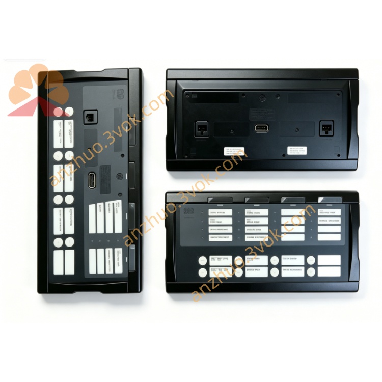
Delomatic‑400 Core Controller: Central processing and power supply module for DM‑4 Land/Marine/Hydro/Wind systems.
High‑Speed Processing: 32‑bit processor (250 MHz) for fast control and protection actionsDEIF.
Multi‑Parameter Measurement: 3‑phase voltage (100–690 VAC), current (1/5 A CT), frequency, power, power factor, and energy monitoring.
Integrated Protection: Over/under voltage, over/under frequency, overload, short‑circuit, reverse power, and earth fault protection.
Rich Communication Interfaces:
Ethernet (WebArm): 10/100 Mbps, TCP/IP, remote monitoring/configuration (default IP: 192.168.2.21)DEIF.
CAN Bus (×3): 125–1000 kbps, for I/O expansion and device communicationDEIF.
RS485 (ARC Network): 2‑wire/4‑wire, 19.2 kbps (DEIF ARC/Modbus RTU)DEIF.
ARCNET: 2.5 Mbps, high‑speed backplane communicationDEIF.
USB: Service interface for firmware updates and configurationDEIF.
PLC‑Style Programmable Logic: Customizable control sequences via DEIF PICUS software.
Event & Alarm Log: 500‑entry time‑stamped log for troubleshooting and compliance.
Marine‑Grade Certified: CE, IEC 60945, DNV‑GL, ABS (marine)DEIF.
Hot‑Swap Compatible: Replaceable without system shutdown (Delomatic‑4 bus support).
3. Technical Specifications
3.1 Electrical Ratings
| Parameter | Specification |
|---|---|
| Model | PCM4.3 (Power and Control Module) |
| Manufacturer | DEIF A/S |
| Part Number | 2044230080A / 2044230081A |
| AC Measurement Inputs | |
| – Voltage | 100–690 VAC, 50/60 Hz (L1/L2/L3), <0.5 mA |
| – Current | 1 A or 5 A CT secondary, <0.3 VA |
| – Accuracy | ±0.2% FS (voltage/current); ±0.1 Hz (frequency) |
| Auxiliary Supply | |
| – Voltage | 24 VDC ±20% (18–32 VDC) |
| – Power | ≤25 W (full load) |
| – Fusing | 5 A slow‑blow (internal) |
| Control Outputs | |
| – Relay Outputs | 8 × 250 VAC / 8 A (resistive), NO/COM |
| – Analog Outputs | 2 × 0–20 mA (load sharing/voltage control) |
| Communication | |
| – Ethernet | 10/100 Mbps, TCP/IP, WebArm (default IP: 192.168.2.21) |
| – CAN Bus (×3) | 125–1000 kbps, ISO 11898‑2 |
| – ARC Network | RS485 (2‑wire/4‑wire, jumper‑selectable), 19.2 kbps |
| – ARCNET | 2.5 Mbps, backplane communication |
| – Node Address | Set via rotary switch S5 (1–F, hex) |
3.2 Environmental & Mechanical
| Parameter | Specification |
|---|---|
| Operating Temperature | –25 °C to +70 °C (standard); –40 °C to +70 °C (marine) |
| Storage Temperature | –40 °C to +85 °C |
| Humidity | 5–95% RH non‑condensing |
| Vibration | 2–13.2 Hz: ±1 mm; 13.2–100 Hz: ±1.0 g (marine) |
| Enclosure | IP20 (front/terminals); conformal coated PCB |
| Dimensions (W×H×D) | 200 × 180 × 50 mm (8TE) |
| Weight | Approx. 0.75 kg |
| Mounting | 35 mm DIN rail (horizontal, leftmost in rack) |
4. Application Scope
Marine Power Systems: Shipboard main/emergency generator control, parallel operation, and dynamic positioning (DP) systems.
Land‑Based Gensets: Industrial standby generators (hospitals, data centers) and grid‑parallel power plants.
Offshore Platforms: Oil/gas rig generators and large motor control (harsh environment, marine‑grade certified).
Renewable Energy: Wind turbine (AWC 400) and hydro turbine (DM‑4 Hydro) control systemsDEIF.
Power Management Systems (PMS): Multi‑genset load sharing, black‑start sequencing, and grid‑island transfer.
Remote Monitoring & Control: WebArm Ethernet connectivity for remote configuration, monitoring, and troubleshootingDEIF.
Retrofit Projects: Upgrade legacy Delomatic‑3 systems to Delomatic‑400 with minimal wiring changes.
5. Installation & Wiring
5.1 Installation Requirements
Mounting: Install on 35 mm DIN rail (horizontal, leftmost in rack) in a ventilated cabinet; ≥50 mm clearance top/bottom.
Environment: Avoid direct sunlight, moisture, corrosive gases, and excessive vibration (use shock mounts for marine).
ESD Protection: Use anti‑static wristband when handling (static‑sensitive PCB).
Cable Separation: Separate high‑voltage measurement cables from low‑voltage communication cables by ≥10 cm.
5.2 Terminal Wiring (Simplified)
| Terminal Group | Description | Wire Gauge |
|---|---|---|
| Auxiliary Power | ||
| 1–2 | 24 VDC (+/−) | 1.5 mm² |
| 3 | Chassis ground (PE) | 2.5 mm² |
| AC Voltage Inputs (L1/L2/L3) | ||
| 4–6 | 100–690 VAC (line‑line) | 2.5 mm² |
| AC Current Inputs (CT1/CT2/CT3) | ||
| 7–9 | 1 A or 5 A CT secondary | 2.5 mm² |
| Relay Outputs (OUT1–OUT8) | ||
| 10–11 | OUT1: NO/COM (breaker close) | 2.5 mm² |
| 12–13 | OUT2: NO/COM (breaker open) | 2.5 mm² |
| 14–15 | OUT3: NO/COM (alarm) | 1.5 mm² |
| 16–17 | OUT4: NO/COM (fault trip) | 1.5 mm² |
| 18–19 | OUT5: NO/COM (aux control) | 1.5 mm² |
| 20–21 | OUT6: NO/COM (aux control) | 1.5 mm² |
| 22–23 | OUT7: NO/COM (aux control) | 1.5 mm² |
| 24–25 | OUT8: NO/COM (aux control) | 1.5 mm² |
| Communication (ARC Network) | ||
| 26–27 | RS485 (A/B, 2‑wire) | 1.0 mm² (twisted‑pair) |
| 28–29 | RS485 (A/B/A’/B’, 4‑wire) | 1.0 mm² (twisted‑pair) |
| CAN Bus | ||
| 30–31 | CAN1 (H/L) | 1.0 mm² (twisted‑pair) |
| 32–33 | CAN2 (H/L) | 1.0 mm² (twisted‑pair) |
| 34–35 | CAN3 (H/L) | 1.0 mm² (twisted‑pair) |
CT Polarity: Strictly match CT phase polarities (L1→L1, L2→L2, L3→L3); never open CT secondary circuits.
Bus Cable: Use twisted‑pair shielded cable for ARC/CAN networks; ground shield at one end only (PCM4.3 side).
Terminal Torque: Tighten terminals to 0.8–1.0 Nm to prevent loose connections and overheating.
Fusing: Protect AC voltage inputs with a 2 A slow‑blow fuse; relay outputs with 10 A max fuses (inductive loads).
5.3 Jumper & Switch Settings
Rotary Switch S5: Set ARC network node ID (1–F, hex); all DGUs must have unique IDs.
Jumper X11: 2‑wire RS485 (default, for multi‑drop networks).
Jumper X12: 4‑wire RS485 (for point‑to‑point communication).
Jumper X13: CAN bus termination (120 Ω, enable at bus ends)DEIF.
6. Front Panel & Operation
6.1 Front Panel Layout
LED Indicators (Left to Right)
POWER: On = 24 VDC supply OK.
RUN: Flashing = Normal operation; Solid = Fault/trip.
COMM: Flashing = ARC network active; Solid = Communication fault.
ETHERNET: Flashing = Ethernet link active; Solid = Link fault.
CAN: Flashing = CAN bus active; Solid = CAN fault.
ALARM: On = Active alarm; Flashing = Unacknowledged alarm.
TRIP: On = Protection trip activated.
LCD Display (16×2 characters):
Top row: Measured values (voltage, current, frequency, power).
Bottom row: Status, alarms, trip messages, and menu options.
Keypad (6 buttons):
▲/▼: Scroll menus/values.
◄/►: Move cursor/select fields.
ENTER: Confirm selection/save settings.
ESC: Exit menu/cancel changes.
6.2 Startup & Configuration
Physical Installation: Mount PCM4.3 on DIN rail; connect 24 VDC, AC inputs, outputs, and communication wiring.
Switch/Jumper Setup: Set S5 node ID; select X11/X12 for RS485 mode; enable CAN termination (X13) if needed.
Power On: Apply 24 VDC; POWER LED on; RUN LED flashes; LCD shows startup screen (DEIF PCM4.3, firmware version).
AC Input Check: Verify voltage/current readings (balanced in healthy condition); frequency = 50/60 Hz.
Nominal Settings (Menu 1000):
Set Nominal Voltage: Match system voltage (e.g., 400 VAC).
Set Nominal Frequency: 50 Hz or 60 Hz.
Set CT Ratio: 1 A or 5 A (match CT secondary).
Protection Settings (Menu 2000):
Overvoltage: 110% Un, 5 s delay.
Undervoltage: 90% Un, 3 s delay.
Overfrequency: 105% fn, 2 s delay.
Underfrequency: 95% fn, 2 s delay.
Overload: 120% In, 10 s delay.
Reverse Power: 5% Pn, 3 s delay.
Genset Control (Menu 3000):
Start/Stop Logic: Configure automatic start on mains failure.
Synchronization: Enable auto‑sync (frequency/phase matching).
Load Sharing: Enable droop or isochronous load sharing.
Communication (Menu 4000):
ARC Network: Enable, set baud rate (19.2 kbps).
Modbus RTU: Enable (optional), set slave address.
Ethernet: Set IP address (default: 192.168.2.21), subnet mask, gateway.
CAN Bus: Enable, set baud rate (250 kbps default).
PC Tool Connection:
USB: Connect PC to USB port; launch PICUS software; verify communication; backup settings.
Ethernet: Connect PC to Ethernet port; open browser; enter default IP (192.168.2.21); log in (user: admin, password: admin)DEIF.
6.3 Normal Operation
LCD Display: Cycles through voltage, current, frequency, power, and status.
RUN LED: Flashes every 1 second (normal).
COMM LED: Flashes every 0.5 seconds (network active).
ETHERNET LED: Flashes every 0.5 seconds (link active).
CAN LED: Flashes every 0.5 seconds (bus active).
ALARM LED: Off (no alarms); On if warning threshold exceeded.
TRIP LED: Off (no trips); On if protection threshold exceeded (breaker opens).
7. Safety Precautions
High Voltage Hazard: Only qualified electrical personnel may install/service. Disconnect all power sources (24 VDC + AC inputs) before wiring.
CT Overvoltage Risk: Never open CT secondary circuits with primary current flowing (lethal voltage). Short CTs before connecting/disconnecting.
ESD Sensitivity: Static electricity can damage internal PCB. Use anti‑static wristband and grounded ESD mat.
Relay Load Ratings: Do not exceed 250 VAC / 8 A per output; inductive loads require external surge suppression.
No Unauthorised Modification: Do not open the enclosure or modify internal circuits. Tampering voids warranty and may cause unsafe operation.
Environmental Limits: Do not operate outside –25 °C to +70 °C (standard) or –40 °C to +70 °C (marine).
8. Maintenance & Storage
8.1 Regular Maintenance (Every 6 Months)
Visual Inspection: Check for loose terminals, damaged wiring, corrosion, or overheating signs (discolouration).
Cleaning: Wipe front panel with dry lint‑free cloth; no liquid cleaners (avoid water ingress).
LED/Display Check: Verify POWER/RUN/COMM/ETHERNET/CAN/ALARM/TRIP LEDs operate correctly; LCD shows clear, legible values.
Measurement Calibration: Compare PCM4.3 readings with external precision meter (accuracy ±0.2% required).
Terminal Tightness: Retorque all terminals to 0.8–1.0 Nm.
Protection Test: Inject overvoltage/overfrequency; verify TRIP LED and breaker operation.
Event Log Backup: Download and save event log via PICUS or WebArm (for trend analysis/troubleshooting).
8.2 Storage Guidelines
Packaging: Store in original anti‑static packaging with desiccant.
Environment: 10–30 °C, 30–70% RH, dry, clean, and dust‑free.
Protection: Avoid direct sunlight, extreme temperatures, and mechanical shock/vibration.
Duration: Shelf life ≤2 years. Inspect for ESD damage and test basic functions before use if stored longer.
9. Troubleshooting
| Fault Phenomenon | Possible Cause | Solution |
|---|---|---|
| POWER LED Off | No 24 VDC / blown internal fuse | Check power wiring; replace 5 A fuse |
| RUN LED Solid (Fault) | AC input fault / CT open circuit / overvoltage | Check voltage/current inputs; short CTs; verify supply |
| COMM LED Solid (Fault) | Wrong S5 node ID / A/B wiring reversed / cable fault | Set unique ID; correct polarity; replace cable |
| ETHERNET LED Off | Cable fault / incorrect IP configuration / link down | Replace cable; verify IP settings; restart networkDEIF |
| CAN LED Solid (Fault) | Bus termination missing / wiring error / baud rate mismatch | Enable X13 termination; correct wiring; match baud rateDEIF |
| ALARM LED On (Overload) | Excessive genset load / CT drift / unbalanced load | Reduce load; check CT connections; balance phases |
| TRIP LED On (Reverse Power) | Genset motoring / synchronization fault / wiring error | Isolate genset; re‑sync; check CT polarity |
| LCD No Display | Faulty LCD / loose display cable / power supply issue | Check power; reconnect display cable; contact DEIF service |
| No Genset Control | Incorrect control logic / faulty relay output / wiring fault | Reconfigure logic; test outputs; check wiring |
| False Tripping | Protection thresholds too low / CT saturation / external fault | Adjust thresholds; check CT rating; verify fault zone |
| WebArm Access Failure | Incorrect IP address / network conflict / firewall block | Verify default IP (192.168.2.21); resolve conflict; disable firewallDEIF |
10. Warranty & Disclaimer
Model: PCM4.3 Power and Control Module (Delomatic‑400).
Warranty Period: 24 months from delivery date (normal installation/use per manual).
Warranty Exclusions: Misuse, overvoltage, lightning, water ingress, unauthorised modification, improper maintenance, or CT/VT faults.
Specifications Subject to Change: Manufacturer reserves the right to update specifications without prior notice.
Liability Limitation: Manufacturer is not liable for indirect or consequential damages (e.g., downtime, lost revenue, equipment damage).
Documentation Version: 1.0 (2026); latest manual and firmware available at www.deif.com.
Get a Quote