Description
1. Product Overview
2. Key Features
3‑Parameter Sync Check: Monitors ΔU, Δf, Δφ with independent adjustable limitsDEIF.
Semi‑Automatic Operation: Enables safe manual/assisted synchronisation.
Dual Analogue Outputs: Δf and ΔU signals for governor/AVR control (to DEIF LSU)DEIF.
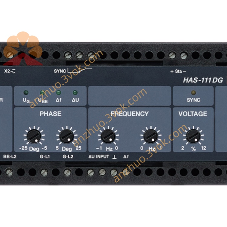
Front‑Panel Adjustment: Five potentiometers for PHASE (two), FREQUENCY, VOLTAGE, and GAINDEIF.
LED Status Indication: Power, control active, and sync OK LEDs.
Wide Input Voltage: 57.7–690 VAC, 50/60 HzDEIF.
Flexible Mounting: 35 mm DIN rail or panel mount.
Isolated I/O: Galvanic isolation between inputs/outputs (3250 VAC, 1 min).
3. Technical Specifications
3.1 Electrical Ratings
| Parameter | Specification |
|---|---|
| Model | HAS‑111DG |
| Function | Semi‑automatic synchroniser / sync check (ANSI 25) |
| Voltage Inputs (Gen/Bus) | 57.7–690 VAC, 50/60 HzDEIF |
| Frequency Range | 40–70 Hz (45/50/60/65 Hz configurable) |
| Control Supply | 24 VDC ±20% (18–32 VDC); 3.5 VA / 2 W |
| Sync Limits (Adjustable) | |
| – Phase Angle | ±1°…±15° (asymmetric possible)DEIF |
| – Slip Frequency | 0.05–0.5 Hz (symmetric/asymmetric)DEIF |
| – Voltage Difference | ±1%…±5% of UnDEIF |
| Outputs | |
| – Sync Relay | 250 VAC / 8 A (closing pulse) |
| – Analogue Outputs | Δf: 0–10 V; ΔU: 0–10 V (to LSU)DEIF |
| – Digital Input | 10–30 VDC (for mode selection) |
3.2 Environmental & Mechanical
| Parameter | Specification |
|---|---|
| Operating Temperature | -20°C to +70°C |
| Storage Temperature | -30°C to +80°C |
| Humidity | 95% RH non‑condensing |
| Vibration | 2–13.2 Hz: ±1 mm; 13.2–100 Hz: ±0.7 g |
| Enclosure | IP20 (front), IP00 (rear) |
| Dimensions (W×H×D) | 144 × 144 × 50 mm |
| Weight | Approx. 0.6–0.75 kg |
| Mounting | 35 mm DIN rail or panel mount |
4. Application Scope
Land‑Based Generators: Standby/prime power for factories, hospitals, data centres.
Semi‑Automatic Synchronisation: Manual synchronisation with supervised check.
Grid Parallel & CHP: Synchronising generators to mains or other gensets.
Marine (Non‑Classed): Emergency/auxiliary generator sync on vessels.
Hybrid Power Plants: Grid connection for diesel‑solar/wind systems.
5. Installation & Wiring
5.1 Installation Requirements
Mounting: Vertical DIN rail or panel mount; ≥50 mm clearance for ventilation.
Environment: Avoid direct sunlight, moisture, corrosive gases, and excessive vibration.
Orientation: Keep upright; do not mount upside down or sideways.
5.2 Terminal Wiring (Simplified)
| Terminal | Description | Wire Gauge |
|---|---|---|
| 1–2 | 24 VDC Power (+/−) | 1.5 mm² |
| 3–4 | Generator Voltage (L1/N) | 1.0–2.5 mm²DEIF |
| 5–6 | Busbar Voltage (L1/N) | 1.0–2.5 mm²DEIF |
| 7–8 | Analogue Output Δf (to LSU) | 1.5 mm²DEIF |
| 9–10 | Analogue Output ΔU (to LSU) | 1.5 mm²DEIF |
| 11–12 | Sync Closing Relay (to Breaker) | 2.5 mm² |
| 13–14 | Digital Input (Mode Select) | 1.5 mm² |
| 15 | Chassis Ground (Earth) | 2.5 mm² |
Use twisted‑pair cables for control signals to reduce noise.
Voltage inputs: connect L1–N (single‑phase) or L1–L2 (3‑phase line‑line)DEIF.
Tighten terminals to 0.8–1.0 Nm; avoid loose connections.
6. Front Panel & Adjustment
6.1 Front Panel Layout
LEDs
POWER: On when 24 VDC is present.
CONTROL: On when analogue outputs (Δf/ΔU) are active.
SYNC: On solid when all sync conditions are met; flashes during synchronisation.
Potentiometers (5)DEIF
PHASE (−): Negative phase limit (e.g., −10°).
PHASE (+): Positive phase limit (e.g., +10°).
FREQUENCY: Max allowable slip frequency (0.05–0.5 Hz).
VOLTAGE: Max allowable voltage difference (±1–5% Un).
GAIN: Analogue output gain (for LSU tuning).
6.2 Recommended Settings (Factory Default)
PHASE: ±10° (symmetric)
FREQUENCY: 0.2 HzDEIF
VOLTAGE: ±2% of UnDEIF
GAIN: Mid‑positionDEIF
7. Synchronisation Procedure (Semi‑Auto)
Power On: Apply 24 VDC; POWER LED lights.
Voltage Matching: Adjust generator AVR to bring ΔU within VOLTAGE pot limit; SYNC LED may flashDEIF.
Frequency Matching: Adjust governor to reduce slip; CONTROL LED active, SYNC flashes faster as Δf decreasesDEIF.
Phase Alignment: The unit monitors phase angle; SYNC LED flashes at slip frequencyDEIF.
Breaker Closure: When ΔU, Δf, Δφ are all within limits, SYNC LED lights solid → close breaker (manual or via contact)DEIF.
8. Safety Precautions
High Voltage Hazard: Only qualified electricians may install/service; disconnect all power before wiring.
Arc Flash Risk: Isolate generator and busbar before working on the synchroniser.
ESD Protection: Use anti‑static wristband when handling the unit.
No Unauthorised Modification: Do not open the enclosure; tampering voids warranty.
Environmental Limits: Do not operate outside -20°C to +70°C; avoid condensation.
9. Maintenance & Storage
9.1 Regular Maintenance (Every 6 Months)
Visual Inspection: Check for loose terminals, damaged wiring, or corrosion.
Cleaning: Wipe front panel with dry cloth; do not use liquid cleaners.
Function Test: Verify ΔU/Δf/Δφ limits and sync operation.
Calibration: Adjust pots if sync accuracy drifts (use precision phase meter).
9.2 Storage Guidelines
Condition: Store in original packaging at 10–30°C, 30–70% RH.
Environment: Keep dry; avoid direct sunlight and extreme temperatures.
Duration: Shelf life ≤2 years; inspect before use if stored longer.
10. Troubleshooting
| Fault Phenomenon | Possible Cause | Solution |
|---|---|---|
| POWER LED Off | No 24 VDC / blown fuse | Check power wiring; replace 2 A fuse |
| SYNC Never Lights | ΔU/Δf/Δφ too large | Adjust VOLTAGE/FREQUENCY/PHASE pots; stabilise genDEIF |
| SYNC Flashes but No Close | Breaker wiring fault / no manual close | Check terminals 11–12; confirm breaker control circuit |
| Analogue Outputs Inactive | GAIN pot too low / LSU wiring fault | Adjust GAIN; check 7–10 wiringDEIF |
| False Sync Alarms | Excessive noise / loose voltage inputs | Use twisted pairs; tighten 3–6 terminals |
11. Warranty & Disclaimer
Model: HAS‑111DG Semi‑Automatic Synchroniser.
Warranty Period: 24 months from delivery date under normal installation and use.
Warranty Exclusions: Damage from misuse, overvoltage, lightning, water ingress, or unauthorised modification.
Specifications Subject to Change: Manufacturer reserves the right to update specifications without prior notice.
Liability Limitation: Manufacturer is not liable for indirect or consequential damages.
Documentation Version: 1.0 (2026); latest manual available at www.deif.com.
Get a Quote