Description
1. Product Overview

2. Key Features
All-in-One Design: Combines paralleling, protection, measurement, and control functions.
High Precision Monitoring: True RMS measurement of voltage, current, frequency, power, and energy.
Comprehensive Protection: Over/undervoltage, over/underfrequency, overcurrent, reverse power, and engine protection.
Seamless Paralleling: Automatic synchronization, load sharing, and bumpless transfer for multiple generators.
Flexible Communication: Modbus RTU (RS-232/485) for PLC/SCADA integration; optional Ethernet.
Intuitive Interface: Backlit LCD with multi-language support; push-button navigation.
Robust Hardware: Wide operating temperature (-20°C to +70°C); high vibration resistance.
Easy Configuration: PC software or front-panel setup; parameter backup/restore.
Scalable System: Network up to 16 units for total plant control.
3. Technical Specifications
3.1 Electrical Ratings
| Parameter | Specification |
|---|---|
| Model | ENERCONGCP3 (GPC-3) |
| Power Supply | 12/24 VDC (9–32 VDC wide range) |
| Power Consumption | ≤ 15 W |
| Voltage Measurement | 100–690 VAC (L-L); 50/60 Hz |
| Current Measurement | 5/5 A CT input; 1–5000 A primary |
| Frequency Range | 45–65 Hz |
| Accuracy | ±0.2% FS (voltage/current); ±0.5% FS (power) |
| Analog Outputs | 2 × 4–20 mA (configurable) |
| Digital Inputs | 8 × isolated (24 VDC) |
| Digital Outputs | 6 × relay (5 A/250 VAC) |
3.2 Environmental & Mechanical
| Parameter | Specification |
|---|---|
| Operating Temperature | -20°C to +70°C (-4°F to +158°F) |
| Storage Temperature | -30°C to +80°C |
| Humidity | 95% RH non-condensing (30–60°C) |
| Vibration | 4 g (10–1000 Hz); compliant with IEC 60068-2-6 |
| Enclosure | IP20 (front); IP00 (rear) |
| Dimensions (W×H×D) | 144 × 144 × 50 mm |
| Weight | Approx. 0.8 kg |
| Mounting | Panel mount (cutout: 138 × 138 mm) |
4. Application Scope
Industrial Generator Sets: Standby/prime power for factories, data centers, and hospitals.
Grid Parallel Systems: Peak shaving, load sharing, and backup power for utility-connected sites.
Renewable Integration: Hybrid systems with solar/wind for stable power output.
Marine & Offshore: Emergency power for vessels and offshore platforms (non-classed).
Critical Infrastructure: Uninterruptible power for airports, telecom, and financial institutions.
5. Installation & Wiring
5.1 Installation Requirements
Mounting: Install vertically on a flat panel; ensure adequate ventilation (≥50 mm clearance around unit).
Environment: Avoid direct sunlight, moisture, and corrosive gases; maintain ambient temperature within -20°C to +70°C.
Vibration: Use shock mounts if installed on engine or high-vibration equipment.
5.2 Wiring Guidelines
Power Supply: Connect 12/24 VDC to terminals 1 (+) and 2 (-); use twisted pair wire (≥1.5 mm²).
Voltage Inputs: Connect L1/L2/L3 and neutral to terminals 3–7; use 1.0–2.5 mm² wire.
Current Inputs: Connect CT secondary (5 A) to terminals 8–13; use 2.5–4 mm² wire; never open CT circuit.
Digital I/O: Connect inputs (24 VDC) to terminals 14–21; connect relay outputs to terminals 22–33 (5 A/250 VAC).
Communication: Connect RS-232 (terminals 34–36) or RS-485 (terminals 37–39) for Modbus RTU.
Grounding: Connect chassis ground (terminal 40) to system earth (≤4 Ω) for ESD protection.
5.3 Wiring Diagram (Simplified)
6. Operation & Configuration
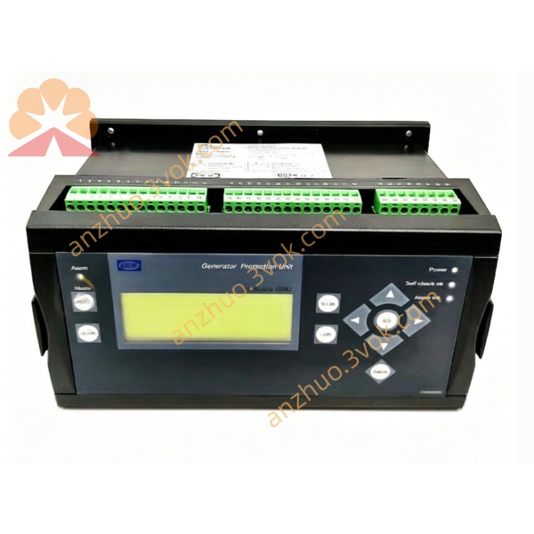
6.1 Front Panel Overview
LCD Display: 4-line backlit screen; shows status, measurements, and alarms.
Push Buttons:
ESC: Exit menu/return to previous screen.
▲/▼: Navigate menus/adjust values.
ENTER: Confirm selection/enter submenu.
ALARM: View active alarms/event history.
6.2 Basic Operation
Power On: Apply DC power; controller initializes (5 seconds) and displays main screen.
Main Screen: Shows generator voltage, frequency, load (kW/% ), and status (Running/Stopped/Alarm).
Menu Navigation: Press ENTER to access main menu (Measurements, Protection, Control, Communication, Settings).
Parameter Adjustment: Select menu → submenu → parameter; use ▲/▼ to change value; press ENTER to save.
Alarm Handling: Press ALARM to view active alarms; resolve fault; press ESC to clear alarm (if fault is reset).
6.3 Configuration Steps (Quick Start)
Set System Parameters:
Language: Select English (default).
System Type: Choose 3-phase 4-wire.
Rated Voltage: Set to 400 VAC (50 Hz) or 480 VAC (60 Hz).
Rated Current: Set CT primary value (e.g., 500 A).
Configure Protection:
Overvoltage: 110% Un (5 s delay).
Undervoltage: 90% Un (5 s delay).
Overfrequency: 52 Hz (5 s delay).
Underfrequency: 48 Hz (5 s delay).
Overcurrent: 125% In (10 s delay).
Reverse Power: 5% Pn (3 s delay).
Set Paralleling Parameters:
Sync Mode: Automatic.
Voltage Match: ±1% Un.
Frequency Match: ±0.1 Hz.
Phase Angle: ±5°.
Load Sharing: Droop 3%.
Communication Setup:
Protocol: Modbus RTU.
Baud Rate: 9600 bps.
Address: 1 (default).
7. Safety Precautions
High Voltage Hazard: Only qualified electricians should install/service this unit; disconnect all power before wiring.
CT Circuit Safety: Never open CT secondary circuit; this causes lethal high voltage.
ESD Protection: Use anti-static wristband when handling controller; avoid touching PCB components.
Environmental Limits: Do not operate outside -20°C to +70°C; avoid condensation.
Vibration Caution: Securely mount unit; excessive vibration may cause damage or false alarms.
Wiring Integrity: Use appropriate wire gauge; tighten terminals to 0.8–1.0 Nm; avoid loose connections.
8. Maintenance & Storage
8.1 Regular Maintenance (Every 6 Months)
Visual Inspection: Check for loose terminals, damaged wiring, or corrosion.
Cleaning: Wipe front panel with dry cloth; do not use liquid cleaners.
Function Test: Verify all protection functions and alarms.
Calibration: Recalibrate voltage/current inputs (if accuracy drifts).
Communication Check: Test Modbus communication with PLC/SCADA.
8.2 Storage Guidelines
Condition: Store in original packaging at 10–30°C, 30–70% RH.
Environment: Keep dry; avoid direct sunlight and extreme temperatures.
Duration: Shelf life ≤ 2 years; inspect before use if stored longer.
9. Troubleshooting
| Fault Phenomenon | Possible Cause | Solution |
|---|---|---|
| No Display | Power supply failure/blown fuse | Check 12/24 VDC; replace fuse (2 A) |
| Voltage Reading Incorrect | Loose voltage wiring/PT error | Check terminals 3–7; verify PT ratio |
| Current Reading Zero | Open CT circuit/wiring fault | Close CT circuit; check terminals 8–13 |
| Frequent Overvoltage Alarms | Voltage regulator fault/incorrect setting | Adjust regulator; check overvoltage threshold |
| Synchronization Failure | Frequency/voltage mismatch/wiring error | Adjust speed/voltage; check sync wiring |
| Communication Loss | Incorrect settings/wiring fault | Verify baud rate/address; check RS-232/485 wiring |
10. Warranty & Disclaimer
Model: ENERCONGCP3 (GPC-3) Generator Paralleling & Protection Controller.
Warranty Period: 24 months from delivery date under normal installation and use.
Warranty Exclusions: Damage from misuse, overvoltage, lightning, water ingress, or unauthorized modification.
Specifications Subject to Change: Manufacturer reserves the right to update specifications without prior notice.
Liability Limitation: Manufacturer is not liable for indirect or consequential damages.
Documentation Version: 1.0 (2026); latest manual available at www.deif.com.
Get a Quote