140XCP60000
Description
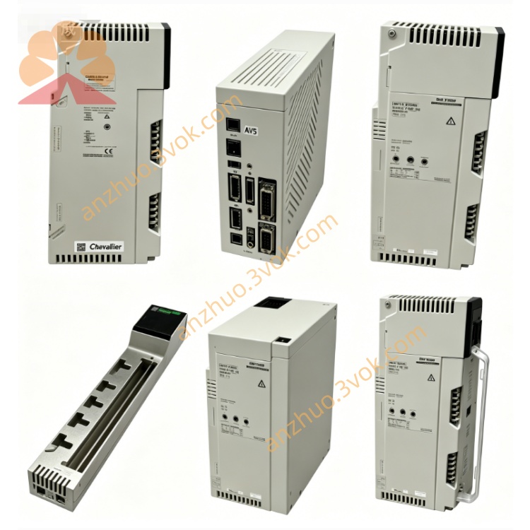
1. Product Description
2. Part Number & Identification
Model: 140XCP60000
Product Line: Modicon Quantum
Type: DC discrete output module (isolated)
Channels: 32 outputs (4 × 8 isolated groups)
Logic: Negative logic (sinking)
Net Weight: 0.3 kg (0.66 lb)
Material: Industrial plastic, flame‑retardant
Country of Origin: France
Certifications: CE, UL, cUL; RoHS compliant
GTIN/EAN: 3595861127456
3. Electrical Specifications
Output Voltage Range: 10–30 VDC
Output Current: 0.5 A per point (max)
Group Current: ≤4 A per group; ≤16 A per module
Power Consumption: 2.5 W + (0.1 W × energized points) + (0.4 W × total load current)
Voltage Drop: 0.4 V @ 0.5 A
Response Time: ≤1 ms (on/off); ≤2 ms (off/on)
Protection: Internal 5 A fuses per group
Surge Current: ≤2.5 A for 1 ms
Backplane Current: 500 mA
4. Mechanical Specifications
Dimensions (H × W × D):
130 mm × 28 mm × 125 mm
5.12 in × 1.10 in × 4.92 in
Protection Rating: IP20 (front face)
Slot Compatibility: All Quantum 140XBP series backplanes (10‑slot, 16‑slot)
Mounting: Standard Quantum backplane slot (hot‑swap compatible)
LED Indicators:
32 × Green LEDs (channel status 1–32)
1 × Red LED (external fault)
1 × Green LED (bus activity)
5. Environmental Ratings
Operating Temperature: 0 °C to +60 °C (non‑condensing)
Storage Temperature: −40 °C to +70 °C (non‑condensing)
Humidity: 5 % to 95 % RH, non‑condensing
Altitude: Up to 2,000 m (6,562 ft) above sea level
Shock: Up to 15G (X, Y, Z axes)
Vibration: IEC 60068‑2‑6 (10–55 Hz)
6. Compatibility
Backplanes: 140XBP01000, 140XBP01600, all Quantum 140XBP series
PLC CPUs: Quantum 140CPU series (e.g., 140CPU67060)
Loads: DC relays, contactors, solenoids, LED indicators (10–30 VDC)
Systems: Modicon Quantum PLC racks, 19” industrial cabinets
7. Installation Instructions
- Pre‑Installation
Ensure backplane slot is empty; system power OFF (or use hot‑swap procedure).
Verify load voltage is 10–30 VDC; check wiring for short circuits.
- Insertion
Align module with empty backplane slot.
Push firmly until module clicks into place.
- Securement
Tighten captive screw to 0.8–1.0 N·m.
Confirm module is flush and secured.
- Wiring
Connect common (+24 VDC) to group terminals.
Connect load negative (–) to output channels.
Use 0.5–1.5 mm² wire; torque terminals to 0.6–0.8 N·m.
- Verification
Power ON; check that green “Bus” LED is lit.
Test each channel via PLC logic; confirm status LEDs match output state.
8. Maintenance
Inspection: Every 6 months – check secure seating, LED status, and terminal tightness.
Cleaning: Wipe with dry cloth; avoid liquids/harsh chemicals.
Fuse Replacement: If red “Fault” LED is on, power OFF and replace internal group fuse (5 A).
Replacement: Replace if damaged, unresponsive, or LEDs fail to indicate.
9. Safety Guidelines
Qualified Personnel Only: Installation by trained electricians/technicians.
De‑Energized Wiring: Connect/disconnect loads only when module power is OFF.
Load Limits: Do not exceed 0.5 A per point or 16 A total module current.
Isolation: Maintain isolation between groups; do not mix voltages.
Ventilation: Keep ≥20 mm clearance above/below for airflow.
10. Warranty
12‑month manufacturer warranty against defects in materials and workmanship.
Get a Quote