140XBE10000
Description
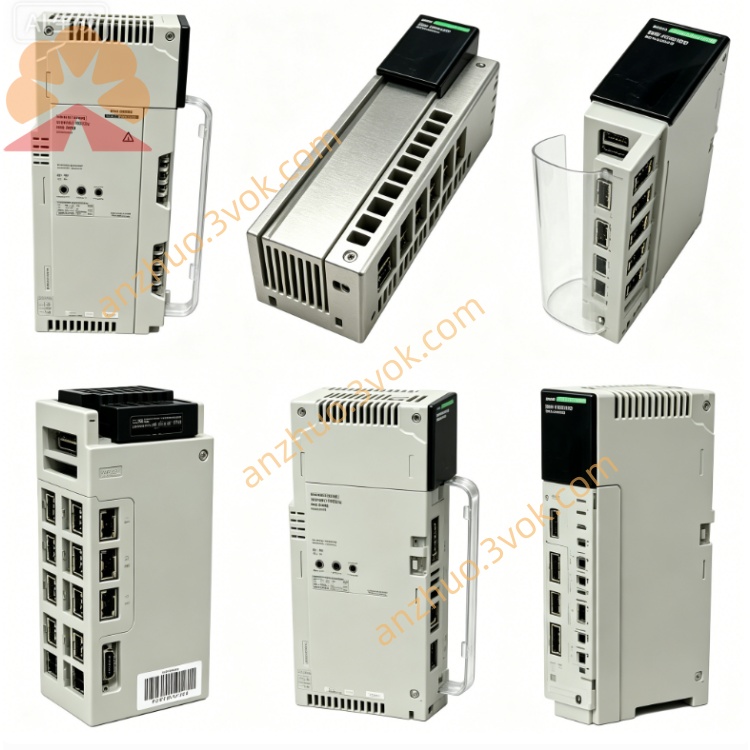
1. Product Overview
2. Key Features
Quantum backplane expansion: supports 12‑slot, 14‑slot, and 16‑slot racks
Backplane communication: 100 Mbps full‑duplex, parallel multi‑module access
Rack‑to‑rack extension: allows cascading of up to 3 levels of expansion racks
Integrated power management: generates and distributes isolated +5 V and ±12 V to I/O modules
Fault isolation: protects main rack from extension rack electrical faults
Hot‑swappable: can be inserted/removed with rack power ON
Diagnostic monitoring: reports voltage rail health and communication status to CPU
Compatibility: works with all standard Quantum I/O modules and CPUs
Certifications: CE, UL, cUL, RoHS compliant
3. Technical Specifications
General
Module type: Backplane expander / bus extension
Supported racks: 12‑slot, 14‑slot, 16‑slot Quantum racks
Expansion levels: up to 3 cascaded extension racks
Backplane bandwidth: 100 Mbps full‑duplex
Backplane voltage: +5 V (logic), ±12 V (I/O)
Current consumption: 100–400 mA @ 24 V DC (external)
Power dissipation: ≤6 W
Electrical Isolation & Protection
Isolation: 1500 Vrms between main and extension backplanes
Overcurrent protection: per voltage rail, self‑resetting
Short‑circuit protection: isolates faults to local rack
Voltage monitoring: under/overvoltage detection for all rails
Environmental
Operating temperature: 0 °C to +60 °C
Storage temperature: −40 °C to +85 °C
Humidity: 10–90 % RH, non‑condensing
Altitude: ≤2,000 m
Protection class: IP20 (module)
Mechanical
Dimensions (W×H×D): 40.34 × 250 × 103.85 mm
Weight: approx. 0.44 kg
Mounting: standard Quantum rack slot
4. LED Indicators
PWR (Green): ON = module powered and 5 V rail OK; OFF = no power or supply fault
RUN (Green): ON = active, communicating with main rack; FLASH = initialization or link fault
FAULT (Red): ON = overvoltage, undervoltage, or short circuit in extension rack; OFF = normal
LINK (Yellow): ON = backplane link established; FLASH = data activity
5. Installation & Wiring
Rack Installation
Insert the 140XBE10000 into an empty slot in the main Quantum rack (typically slot 0 or last slot).
Push firmly until the module latches into place.
For multi‑rack systems, connect the extension rack backplane cable to the expander’s dedicated port.
Secure all cables and ensure proper grounding.
Power Wiring
External 24 V DC: connect to module’s V+ and 0 V terminals
Ground: connect module chassis to system earth ground
Cable: use twisted pair, 18–24 AWG, max length 500 m
System Grounding
Separate signal ground from power ground
Single‑point earth ground for all racks
Shield cables at one end only
6. Configuration (Unity Pro)
Open Unity Pro V7.0 or later.
In the hardware configuration, add 140XBE10000 to the main rack.
Define the number of extension racks and slots per rack.
Enable backplane diagnostics and fault reporting.
Map I/O modules in extension racks to the CPU I/O image.
Download the configuration to the CPU; the expander initializes automatically.
7. Operation & Diagnostics
Normal Operation
PWR: ON
RUN: ON
FAULT: OFF
LINK: ON (steady or flashing)
Fault Conditions
FAULT ON: Check extension rack wiring, short circuits, or I/O module failures. The expander shuts down power to the extension rack to protect the main system.
RUN Flashing: Verify backplane cable connection, seating of the expander, or CPU configuration.
PWR OFF: Check external 24 V DC supply and wiring.
Diagnostic Data
The expander provides status words to the CPU, including:
Voltage rail status (+5 V, ±12 V)
Backplane link quality
Overcurrent/short‑circuit flags
Module temperature
8. Maintenance
Monthly: Inspect LED status and cable connections
Quarterly: Verify torque on terminal blocks; clean module vents
Semi‑annually: Test fault isolation by simulating a short in an extension rack
Firmware: Update via Unity Pro as recommended by Schneider Electric
9. Safety & Compliance
Qualified personnel only for installation, wiring, and maintenance.
Disconnect all power before servicing the module or rack.
This module is for industrial control systems only; not for direct life‑safety applications without additional safety layers.
Follow all local electrical codes and safety regulations.
10. Compatibility
Quantum CPUs: 140CPU65150, 140CPU67160, 140CPU68060, 140CPU69060 and later
Software: Unity Pro V7.0+, Concept V2.6+
I/O modules: all standard Quantum digital/analog I/O, safety, and specialty modules
Get a Quote