Detailed Product Description of XYCOM XVME-203
Description
Detailed Product Description of XYCOM XVME-203
I. Product Overview
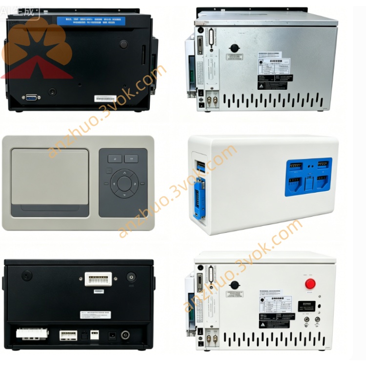
XVME-203 is a 3U single-height VMEbus high-speed quadrature counter/timer module launched by XYCOM (now belonging to Acromag/Xembedded). Its core is targeted at encoder position feedback, high-speed pulse counting, motion control and timing generation scenarios. It integrates two AM9513A counter chips and quadrature decoding circuits, and is the core I/O module for high-precision motion measurement and control in VME systems. Core positioning
As a VMEbus slave device, the XVME-203 focuses on the integrated capabilities of "multi-channel high-speed counting + orthogonal encoder direct connection + programmable pulse output + flexible interrupts", suitable for 3U VME chassis, and solves the requirements of position, speed, frequency measurement and pulse generation in motion control with a single slot. The derivative model of this series is XVME-293 with a 6U specification.
II. Core Functional Characteristics
1. Standard VMEbus interface (fully compatible design)
Fully complies with the IEEE 1014 VMEbus Rev. C.1 specification, compatible with all 3U VME chassis and backplanes, operating in slave device mode. The address space uses A16 (64KB), the base address is flexibly configured through onboard jumpers in A10–A15 bits, occupying a fixed 256-byte address range to avoid system address conflicts. Data width supports D08 (O)/D16, compatible with 8-bit and 16-bit data transmission, suitable for different bit-width VME master controllers. It has complete VME interrupt capability, supported by the AM9519A interrupt controller for IRQ1–IRQ7 interrupt lines, 8 interrupt channels can be configured as unified vectors or independent vectors, interrupt priority can be programmed, responding to events such as count completion, overflow, output pulse completion, etc. The backplane connection only requires P1 connector, without the need for P2 auxiliary interface, simplifying the chassis wiring.
2. 10 channels of 16-bit high-speed counters (core function)
Equipped with 2 AM9513A timers/counters chips, providing 10 independent 16-bit counting channels, each channel's maximum count value is 65535, supporting software configuration as addition counting, subtraction counting, bidirectional counting. The highest counting frequency reaches 5MHz, supporting single pulse, double pulse, and AB phase orthogonal three input modes, compatible with TTL level pulse signals and incremental encoder signals. Input channels have buffer circuits, input characteristics are low-level suction 200μA, high-level output 20μA, with strong anti-interference ability, compatible with industrial field sensors and encoder outputs. Each channel can independently configure counting mode, trigger edge (rising edge / falling edge), counting range, supporting loop counting, single counting, gate counting, suitable for frequency measurement, cycle measurement, event counting, rotational speed calculation, etc.
3. 4 channels of orthogonal decoding (encoder direct connection)
Built-in 4 independent orthogonal decoding circuits, capable of simultaneously connecting 4 incremental encoders, directly processing A/B phase orthogonal signals, without the need for external decoding modules. Supports quadruple frequency decoding, increasing the basic counting rate from 5MHz to equivalent 20MHz, significantly improving position measurement accuracy, suitable for high-precision servo, stepper motor position feedback. In orthogonal mode, the rotation direction is automatically identified (forward / reverse), real-time output position increments, supports position closed-loop control, travel limit triggering, origin return, etc. in motion control functions.
4. 8 channels of programmable TTL output channels
Provide 8 TTL-level output channels, each channel can be independently programmed and configured, supporting frequency output, single pulse (One-shot), frequency division output, pulse sequence generation, PWM modulation. The output drive capability is 15mA current sinking, 24mA current sourcing, capable of directly driving TTL loads, small relays, indicator lights, and pulse command ends of servo/stepper drivers. The output channels are linked with the counters, allowing setting to trigger output pulses when the counter reaches a preset value, or generating fixed-frequency pulses to drive the motor, suitable for pulse command output, timing triggering, alarm output, etc. in motion control scenarios.
5. Flexible Interrupts and Status Monitoring
Integrate the AM9519A universal interrupt controller, providing 8 interrupt sources, which can be configured as: completion of counting interrupt, overflow interrupt, orthogonal signal error interrupt, output pulse completion interrupt, gate control signal change interrupt, etc. The interrupt response mode supports ROAK (Release On Acknowledge), ensuring efficient interrupt handling and supporting multi-level interrupt priority scheduling to meet the fast response requirements of real-time motion control. All counting channels, output channels, and interrupt status can be read through software, and real-time monitoring of counting values, output states, and interrupt flags is possible, facilitating fault diagnosis and state traceability.
6. Industrial-grade High Reliability Design
Standard operating temperature range: 0℃ to +70℃, storage temperature range: -40℃ to +85℃. It can be extended to wide temperature conditions, suitable for industrial sites, outdoor equipment, and other harsh environments. The anti-vibration and anti-shock capability complies with industrial standards, capable of withstanding 1g (10–100Hz) vibration and 15g impact, adapting to the vibration scenarios during equipment operation. The EMC performance is compliant, passing CE/FCC Class A certification. The circuit board uses gold-plated gold fingers and shielding design to reduce electromagnetic interference and improve the long-term stability of the system. Low power consumption, typical operating power consumption +5V@0.8A (approximately 4W), low heat generation, no need for additional heat dissipation modules, suitable for enclosed chassis environments.
7. Panel Status Indicator Lights
The front panel is equipped with multiple groups of LED indicator lights, which visually display the module operation and channel status: POWER indicator light, always on when power is normal; RUN indicator light, always on when power-on self-test passes and the module is running normally, flashes when there is a fault; INT indicator light, flashes when a VME interrupt is triggered; CH0–CH9 ACT indicator lights, flash when a pulse input is detected by the corresponding counting channel; OUT0–OUT7 ACT indicator lights, flash when the corresponding output channel is activated.
III. Hardware Specifications Details
Bus Interface Specifications
Bus Protocol: IEEE 1014 VMEbus Rev. C.1, slave device mode;
Address Space: A16 (64KB), 256-byte window, jumper configuration base address;
Data Width: D08 (O)/D16;
Interrupt Support: IRQ1–IRQ7, 8 interrupt channels, programmable vector / priority;
Backplane Interface: P1 connector.
Counting Channel Specifications
Core Chip: 2×AM9513A timer / counter;
Total Number of Channels: 10 independent 16-bit counters;
Maximum Count Value: 65535;
Maximum Count Frequency: 5MHz (single / double pulse), 20MHz (quadruple frequency of orthogonal);
Input Mode: Rising edge / falling edge triggering, add / subtract / bidirectional counting, AB orthogonal;
Input Level: TTL compatible (high ≥ 2.0V, low ≤ 0.8V);
Input Buffer: low-level sinking 200μA, high-level output 20μA.
Orthogonal Decoding Specifications
Decoding Channels: 4 independent orthogonal decoding;
Encoder Type: Incremental (A/B phase);
Decoding Multiplication: 1x / 4x (software selectable);
Direction Recognition: Automatic forward / reverse judgment.
Output Channel Specifications
Total Number of Channels: 8 TTL outputs;
Output Function: frequency output, single pulse, division, PWM, pulse sequence;
Drive Capacity: 15mA current injection, 24mA current pull-up;
Output Level: TTL compatible (high ≥ 2.4V, low ≤ 0.4V).
Electrical and Environmental Specifications
Power Supply: +5V DC ±5%, typical current 0.8A; Operating temperature: 0℃ to +70℃;
Storage temperature: -40℃ to +85℃;
Vibration resistance: 1g (10–100Hz);
Impact resistance: 15g;
Size: 3U (100mm×160mm), single slot;
Weight: approximately 0.38kg.
IV. Typical Application Scenarios
1. Motion Control (Servo / Stepper Motors)
Directly connect 4 incremental encoders to achieve multi-axis position feedback and closed-loop control; 8 output channels output pulse instructions to drive servo / stepper motors, suitable for multi-axis motion control of semiconductor equipment, machine tools, and robots, supporting position positioning, speed control, and synchronous movement.
2. High-speed Pulse Counting and Frequency Measurement
Used for product counting in production lines, encoder rotational speed measurement, flow pulse counting, high-frequency signal frequency / period measurement. 10 channels can simultaneously monitor multiple nodes, with a 5MHz counting frequency suitable for high-speed sensors and pulse sources.
3. Precise Timing and Pulse Generation
Using programmable output channels to generate high-precision single pulses, timing pulse sequences, PWM signals, suitable for timing triggering, synchronous control, valve opening adjustment, motor speed regulation, etc., without the need for additional timing modules.
4. Equipment Status Monitoring and Fault Alarm
Connect limit switches, proximity switches, speed sensors to collect equipment position, speed, and operating status; through interrupts, respond to abnormalities (such as overspeed, overtravel) in real time, trigger alarm output or emergency shutdown to ensure equipment safety.
5. Upgrading of Old VME Motion Systems
Directly replace the counting module in the old system, without modifying the VME chassis architecture and main program, to upgrade the counting accuracy and channel quantity, extending the service life of old VME equipment in semiconductor, military, industrial control, etc.
V. Installation and Programming Key Points Installation steps
Preparations: Ensure that the P1 slot of the VME chassis is intact and the +5V power supply is stable; Prepare TTL encoder/sensor cables and check the pin definitions.
Jumper configuration: According to the system address planning, set the A10–A15 base address jumper; Configure interrupt vectors, priorities, and match system interrupt management.
Module insertion: Align the XVME-203 to the 3U slot and push it in smoothly to ensure good contact of the gold fingers, and tighten the panel screws for fixation.
Cable connection: Connect the encoder A/B phase and pulse input signals to the counting channel, connect the output channel to the driver / relay, and check the wiring to avoid misconnection.
Power-on self-test: After the chassis is powered on, the POWER and RUN indicator lights are constantly on, without error flashes, indicating that the module self-test is passed and the operation is normal.
Programming process (simplified)
Address mapping: Configure the A16 base address, map the module registers to the system memory, and establish CPU and module communication.
Counting channel configuration: Select the channel number, set the counting mode (addition / subtraction / bidirectional), trigger edge, counting range, and enable orthogonal decoding (if necessary).
Output channel configuration: Select the output channel, set the function (frequency / single pulse / PWM), pulse width, frequency, trigger condition (such as when counting to N value).
Interrupt configuration: Enable the interrupt source (count completion / overflow / output completion), set the interrupt vector and priority, and write the interrupt service program.
Data reading and control: Read the real-time values and status flags of the counting channel; Control the output channel to start or stop, and respond to interrupts to execute corresponding actions (such as positioning completion, alarm).
Six. Core advantages
1. Multi-channel integration, high functional density
10 high-speed counters + 4 orthogonal decoders + 8 programmable outputs, a single slot covers counting, position feedback, pulse generation, and timing control, without the need for multiple module combinations, saving chassis slots and costs.
2. High speed and high precision, suitable for precise motion
5MHz base counting, 20MHz orthogonal quadruplex frequency, 16-bit counting accuracy, meeting the requirements of high-speed and high-precision motion control and measurement, suitable for semiconductor, machine tools, etc. precision equipment.
3. Flexible programmability, suitable for multiple scenarios
Counting mode, output function, interrupt trigger can be configured through software, without hardware modifications, quickly adapting to counting, motion control, timing generation and other different scenarios, shortening the debugging cycle.
4. Industrial-grade reliability, stable in harsh environments
Wide temperature, anti-vibration, anti-interference design, gold-plated gold fingers and shielding process, suitable for industrial sites, outdoors, military and other harsh environments, long-term operation stable, low maintenance costs.
5. Strong compatibility, easy integration and upgrade
Standard VMEbus interface, directly compatible with existing VME systems; encoder / sensor direct connection, no need for external circuits, simple integration; sufficient spare parts for discontinued products, suitable for maintenance and upgrade of old systems.
Seven. Precautions
The module is discontinued. When purchasing, prefer to choose second-hand / refurbished spare parts with complete test reports, check the model 70203-001 and version, to avoid faulty or incompatible modules.
Inputs / outputs are all TTL level, cannot be directly connected to 24V industrial signals, need to be converted through a level conversion module, to avoid burning the channel chip.
Orthogonal encoders wiring needs to be shielded, away from power cables, to reduce electromagnetic interference; for long-distance wiring, it is recommended to use differential signal transmission to improve stability.
Operating temperature 0℃~+70℃, when installing, ensure good ventilation of the chassis, avoid heat accumulation; in high-temperature environments, it is recommended to reduce the counting frequency to extend the module lifespan. During installation and maintenance, proper static protection measures must be taken. Wear anti-static wristbands and operate on an anti-static workbench to prevent static electricity from damaging the chips.
Get a Quote