399D915G05
Description
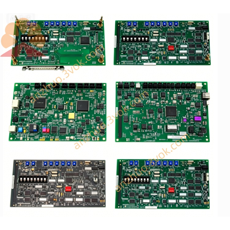
1. Product Overview
Model Code Definition
399D: WDPF system input module series code
915: internal hardware circuit version number
G05: firmware software revision grade
2. Electrical & Technical Specifications
| Item | Parameter |
|---|---|
| Power Supply | +5VDC / ±15VDC from DCS rack backplane bus |
| Input Signal Type | Standard 4–20mA DC analog current signal, 0–10VDC voltage input, field transmitter signal compatible |
| Input Channel | Multi-channel isolated analog input (standard factory configuration) |
| Signal Processing | Built-in RC filter + programmable gain amplification, anti-surge & EMI interference suppression circuit |
| Isolation | Galvanic isolation between field input and internal control circuit |
| Communication Interface | Parallel backplane bus for data exchange with WDPF main controller |
| Operating Temp | 0℃ ~ +55℃ (in rack working); -40℃ ~ +85℃ storage temperature |
| Mounting Format | Standard Eurocard plug-in design, slot installation inside WDPF rack cabinet |
| Certification | UL, CE industrial automation standard certified |
3. Main Product Features
High-precision analog-to-digital conversion, stable sampling accuracy under harsh industrial electromagnetic environment.
On-board fault diagnosis circuit with channel open/short-circuit detection, fault status uploaded to DCS host for alarm display.
Compact single-board structure, hot-plug compatible with matched WDPF rack slots for convenient replacement and maintenance.
Rugged industrial-grade PCB layout, dust-proof and anti-vibration design for long-term continuous running in power plant control room.
4. Typical Application
Thermal power plant boiler, turbine DCS distributed control system
Petrochemical refining production process monitoring & signal collection
Metallurgy furnace continuous production centralized control
Large industrial water treatment automatic control system
5. Installation & Operation Guide
Power off target rack slot before module plug-in, insert vertically into designated WDPF rack card slot and lock fixing latch.
Confirm backplane power specification matches module rated supply voltage before rack energization.
Wire field 4–20mA / 0–10V sensor signal to corresponding module terminal per wiring diagram, strictly follow positive-negative polarity requirement.
After power-on, check DCS upper computer for normal real-time data reading; abnormal channel indicates wiring fault or module damage.
Regular dust cleaning on module surface every 6 months to prevent poor heat dissipation caused by accumulated dust.
Get a Quote