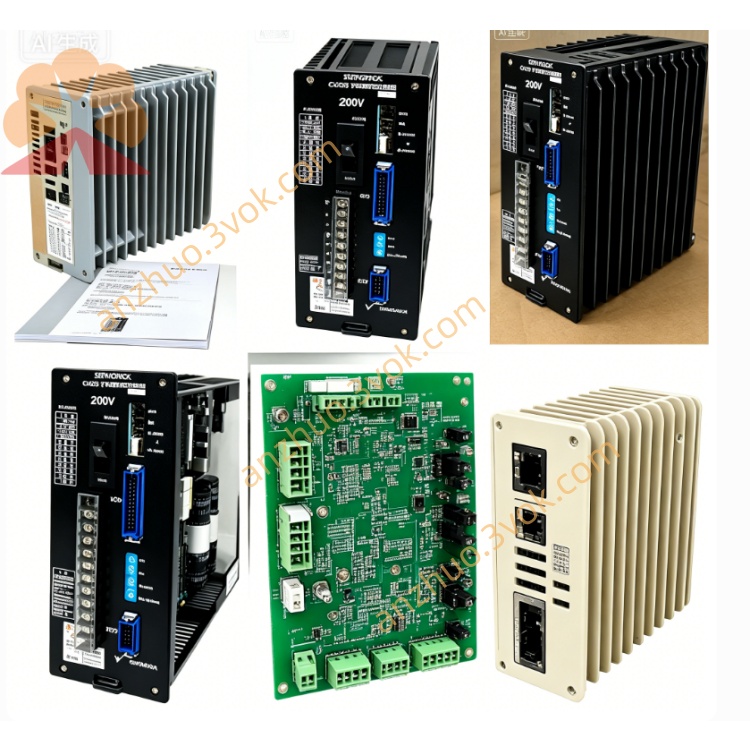
CACR-SR15BB1BF-Y100
CACR represents Yasnac VS800 full digital AC servo drive specially customized for OEM CNC machine feed axes.
SR means the hardware is equipped with dual command input circuit including ±10VDC analog signal and differential pulse signal, while actual available function is restricted by Y100 customized firmware.
15 stands for rated output power 1.5kW under AC200V specification, continuous rated output current is 9.7Arms.
BB refers to standard universal main control PCB and common I/O peripheral circuit layout.
1 means three-phase AC200~230V main power input specification, with independent single-phase AC200V supplied for control power separately.
BF indicates CN2 connector is exclusively designed for incremental optical encoder without built-in backup battery circuit for absolute position.
Y100 is exclusive OEM customized firmware version. Core application parameters and I/O definition are pre-solidified and locked at factory, unauthorized parameter modification is prohibited for end users.
Description
1. Model Code Definition
CACR represents Yasnac VS800 full digital AC servo drive specially customized for OEM CNC machine feed axes.SR means the hardware is equipped with dual command input circuit including ±10VDC analog signal and differential pulse signal, while actual available function is restricted by Y100 customized firmware.15 stands for rated output power 1.5kW under AC200V specification, continuous rated output current is 9.7Arms.BB refers to standard universal main control PCB and common I/O peripheral circuit layout.1 means three-phase AC200~230V main power input specification, with independent single-phase AC200V supplied for control power separately.BF indicates CN2 connector is exclusively designed for incremental optical encoder without built-in backup battery circuit for absolute position.Y100 is exclusive OEM customized firmware version. Core application parameters and I/O definition are pre-solidified and locked at factory, unauthorized parameter modification is prohibited for end users.
2. Basic Electrical Specifications
Three-phase main input voltage ranges AC200V~230V with permissible fluctuation from minus 15% to plus 10%, applicable for both 50Hz and 60Hz power supply.Overload characteristic: 150% rated current can run continuously for 60 seconds; instantaneous 300% peak overload is limited within 3 seconds during motor startup.Nominal DC bus working voltage is DC280V~320V; terminals P and BN are reserved for external regenerative braking resistor connection for frequent rapid deceleration and emergency stop conditions.The drive adopts IGBT sine-wave PWM modulation with maximum output frequency of 300Hz, protection grade IP20 for vertical cabinet installation only, net unit weight is around 3.3kg.
3. Exclusive Custom Features of Y100 Version
Factory locks the control mode permanently as ±10VDC analog speed control; pulse position control and torque control functions are disabled by firmware and cannot be switched on by local parameter setup.Incremental encoder resolution is pre-fixed to designated value according to matched OEM servo motor; users are unable to revise encoder pulse count via parameters.Position loop gain, speed loop gain, acceleration and deceleration time, anti-vibration filter parameters are pre-calibrated and write-protected; on-site auto-tuning is partially blocked and full automatic motor identification is unavailable.CN1 digital I/O pin assignment follows fixed Y100 OEM definition, all I/O functions cannot be redefined by modifying internal parameters, different from open standard BF model.Onboard RS422 communication only allows checking real-time operating data and historical fault records; locked core parameters cannot be uploaded or rewritten through communication cable.
4. Installation and Environmental Requirements
Operating ambient temperature ranges 0℃~+55℃; storage temperature is between -20℃~+70℃. Working humidity maintains 5%~80%RH without condensation. Reduce output load when installation altitude exceeds 1000 meters above sea level.Anti-vibration specification: 10~55Hz with single amplitude 0.5mm. Reserve more than 50mm ventilation gap on top and bottom of servo inside control cabinet for heat dissipation.Cut off all AC power and wait at least 15 minutes for full discharge of internal DC bus capacitor before disassembling cover or plugging connectors; hot plug of CN1 and CN2 under powered state is strictly forbidden.
5. Terminal and Connector Description
R/S/T terminals connect three-phase main AC input power; U/V/W terminals link three-phase power cable of servo motor.P and BN terminals are used for external regenerative braking resistor wiring to consume surplus regenerative energy during rapid deceleration.CN1 is opto-isolated digital I/O connector with fixed Y100 OEM signal mapping, adjustable I/O definition is unavailable.CN2 is dedicated incremental encoder feedback port which only matches original designated incremental servo motor specified by Y100 standard.Front seven-segment LED displays real-time running status and standard VS800 series fault codes.
6. Built-in Protection Functions
Complete protection covers overcurrent, DC bus overvoltage, DC bus undervoltage, drive overheat, encoder disconnection, motor overload and CPU abnormal operation protection. The latest ten fault codes are permanently stored in memory without data loss after power off or fault reset.Internal dynamic brake circuit is integrated for regular deceleration energy dissipation; external regenerative resistor must be installed between P and BN terminals under heavy cyclic load and frequent emergency stop working condition.
7. Replacement and Maintenance Instructions
Only identical full model CACR-SR15BB1BF-Y100 supports direct plug-and-play replacement. Ordinary non-Y suffix standard CACR-SR15BB1BF cannot substitute directly due to different locked firmware and fixed I/O logic; replacement requires professional factory to rewrite Y100 customized program.Check tightness of all power wiring and CN1/CN2 connectors before every startup; clean radiator cooling fin dust every three to six months to avoid overheat shutdown caused by poor heat dissipation.Full factory parameter initialization is strictly prohibited for Y100 model, this operation will erase OEM preset fixed parameters and lead to abnormal machine running.
8. Common Fault Troubleshooting
Overheat alarm results from clogged radiator dust, poor cabinet ventilation or continuous overload; solve by cleaning cooling structure or reducing actual operating load.Encoder fault occurs when CN2 connector is loose, feedback cable is damaged or mismatched non-designated motor is connected; inspect wiring and replace matched original incremental motor.Overvoltage alarm during rapid deceleration can be eliminated by installing external braking resistor between P and BN terminals.Parameter write failure is caused by attempting to revise firmware-locked Y100 core parameters, which belongs to normal software protection instead of hardware failure.Overload alarm is triggered by mechanical jamming or excessive payload; inspect mechanical transmission structure and cut down equipment load accordingly.
9. Fault Code Definition
1=Overcurrent fault2=Main circuit abnormal3=DC bus overvoltage4=DC bus undervoltage5=Drive overheat6=Encoder disconnection7=Motor overloadA=CPU operation faultC=External emergency stop input active
Get a Quote