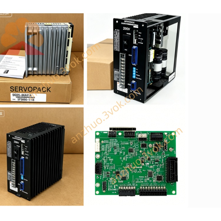
CACR-SR15BB1AF-Y8
CACR = Yasnac VS800 full digital AC Servopack for CNC machine feed axis application.
SR = Dual command support: ±10VDC analog speed/torque input + differential pulse position input, parameter-switchable in standard version but fixed mode under Y8 customization.
15 = Rated power 1.5kW, AC200V class, continuous rated output current 9.7Arms.
BB = Standard mainboard & universal I/O base circuit PCB layout.
1 = Three-phase AC200~230V main power input specification, independent single-phase AC200V control power supply.
AF = Incremental encoder receiving circuit for dedicated matching Yas incremental pulse servo motor.
Y8: Exclusive OEM fixed-parameter custom variant, pre-programmed for designated CNC factory equipment, core motion parameters locked inside factory firmware, manual parameter revision forbidden by end-user.
Description
1.Model Coding Definition
CACR = Yasnac VS800 full digital AC Servopack for CNC machine feed axis application.SR = Dual command support: ±10VDC analog speed/torque input + differential pulse position input, parameter-switchable in standard version but fixed mode under Y8 customization.15 = Rated power 1.5kW, AC200V class, continuous rated output current 9.7Arms.BB = Standard mainboard & universal I/O base circuit PCB layout.1 = Three-phase AC200~230V main power input specification, independent single-phase AC200V control power supply.AF = Incremental encoder receiving circuit for dedicated matching Yas incremental pulse servo motor.Y8: Exclusive OEM fixed-parameter custom variant, pre-programmed for designated CNC factory equipment, core motion parameters locked inside factory firmware, manual parameter revision forbidden by end-user.
2.General Electrical Specifications (Same hardware as standard CACR-SR15BB1AF, only firmware customized for Y8)
Three-phase main input AC200V~230V, permissible voltage deviation -15%~+10%, 50/60Hz universal frequency. Separate single-phase AC200V feeds control power circuit independently.Overload capability: 150% rated current continuous operation for 60s, 300% peak overload limited within 3s during startup.DC bus nominal voltage DC280V~320V; terminals P & BN reserved for external regenerative braking resistor wiring for frequent deceleration working condition.IGBT sine-wave PWM modulation, max output frequency 300Hz, protection grade IP20 for vertical cabinet installation only, net unit weight around 3.4kg.
3.Unique Custom Features of Y8 Version
Default fixed control mode: factory locked analog ±10V speed control for CNC host analog output; pulse position control function is disabled by firmware and cannot be activated via local parameter setting.Position loop gain, speed loop gain, acceleration/deceleration time constant, electronic gear ratio and anti-resonance filter parameters are solidified according to OEM machine mechanical feature, all locked without modification access.CN1 I/O pin assignment fixed by Y8 factory definition, differs from standard AF general model; digital input/output functions cannot be redefined through parameter adjustment.Encoder matching locked for specified pulse-count Yas servo motor; replacing with non-designated motor triggers continuous PG disconnect alarm immediately.Motor auto-tuning function partially blocked: full automatic parameter identification is invalid; only tiny current loop fine adjustment available on site.RS422 serial communication allows reading running data and historical fault logs, yet prohibits uploading/downloading or rewriting locked core parameters.
4.Installation & Environmental Requirements
Operating ambient temperature: 0℃~+55℃; storage temperature: -20℃~+70℃; working humidity 5%~80%RH with no condensation. Derate output load when mounting altitude over 1000m above sea level.Anti-vibration specification: 10~55Hz vibration, single amplitude 0.5mm. Keep minimum 50mm vacant space on top and bottom of servo for heat dissipation inside control cabinet.Cut all AC input power and wait minimum 15 minutes for internal DC bus capacitor full discharge before cover opening or connector wiring; never hot-plug CN1 and CN2 connectors under powered state.
5.Terminal & Connector Description
R/S/T: three-phase main AC power input; U/V/W: three-phase servo motor power wiring terminals.P-BN: external regenerative braking resistor connection terminals to consume regenerated energy during rapid deceleration and emergency stop.CN1: opto-isolated digital I/O connector with fixed Y8 OEM pin definition, no editable I/O mapping.CN2: dedicated incremental encoder feedback connector locked for matched original factory motor only.Front panel single-digit seven-segment LED displays real-time operating status and all fault codes, identical fault code definition as standard VS800 series.
6.Protection Functions
Complete full-range protection: output overcurrent, DC bus overvoltage, DC bus undervoltage, drive overheat, encoder disconnection, motor overload, CPU abnormal fault. Latest ten fault records stored permanently in memory without power-loss data disappearance.Built-in internal dynamic brake circuit; external braking resistor must be mounted between P and BN under heavy cyclic load and frequent emergency stop application to eliminate deceleration overvoltage fault.
7.Replacement & Maintenance Rules
Direct replacement only accepts identical full model CACR-SR15BB1AF-Y8. Ordinary non-Y suffix standard CACR-SR15BB1AF cannot substitute directly due to locked parameter and fixed I/O difference; replacement needs manufacturer to rewrite Y8 dedicated firmware professionally.Regular pre-start inspection: check tightness of power cable and CN1/CN2 plug connections; clean radiator dust every 3~6 months to avoid overheat shutdown caused by poor heat dissipation.Factory full parameter reset operation is strictly prohibited on Y8 unit, reset will erase OEM locked custom data and result in machine abnormal running.
8.Common Troubleshooting Guidance
Overheat alarm: caused by clogged radiator dust, insufficient cabinet ventilation or long-term overload; resolve via cleaning cooling fins or lowering actual working payload.Encoder fault: loose CN2 plug, damaged feedback cable or mismatched non-original motor; inspect wiring and use designated matched motor only.Overvoltage alarm during quick deceleration: install external braking resistor across P and BN terminals.Parameter error alarm: triggered by unauthorized parameter modification; restore original setting via professional factory setup only.Overload alarm: mechanical jamming or excessive load; check transmission mechanical structure and reduce equipment load accordingly.
9.Fault Code Definition
1=Overcurrent, 2=Main circuit failure, 3=DC bus overvoltage, 4=DC bus undervoltage, 5=Drive overheat, 6=Encoder break,7=Motor overload, A=CPU malfunction, B=Parameter mismatch, C=External emergency stop input triggered.
Get a Quote