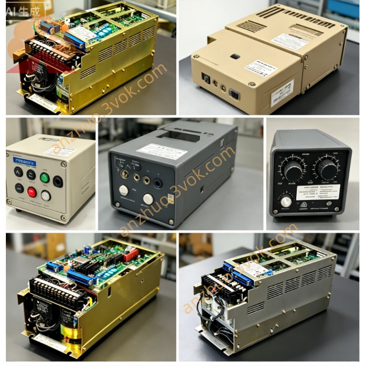
CACR-SR12TB6CSE
CACR: Yasnac VS800 full digital AC servo amplifier for CNC and automated equipment closed-loop control
SR: Three switchable control modes via parameter: ±10VDC analog speed / torque control, optional pulse position control
12: Rated power 1.2kW, AC200V class; continuous rated output current:11.7Arms
T: Standard CNC general mainboard design (non-robot SZ series PCB)
B: Dual command input hardware: ±10VDC analog + differential line-driver pulse position input available
6: Custom fixed control power peripheral circuit with partial pre-set base parameters at factory
C: Customized encoder interface circuit, compatible with specified external encoder wiring definition different from standard A/B type
S: Standard adjustable base firmware with partial I/O preset; most gain parameters user-modifiable, few core factory parameters write-protected
E: End-user OEM customized version for specific machine model, fixed application-oriented default settings
Description
1. MODEL CODE DEFINITION
CACR: Yasnac VS800 full digital AC servo amplifier for CNC and automated equipment closed-loop controlSR: Three switchable control modes via parameter: ±10VDC analog speed / torque control, optional pulse position control12: Rated power 1.2kW, AC200V class; continuous rated output current:11.7ArmsT: Standard CNC general mainboard design (non-robot SZ series PCB)B: Dual command input hardware: ±10VDC analog + differential line-driver pulse position input available6: Custom fixed control power peripheral circuit with partial pre-set base parameters at factoryC: Customized encoder interface circuit, compatible with specified external encoder wiring definition different from standard A/B typeS: Standard adjustable base firmware with partial I/O preset; most gain parameters user-modifiable, few core factory parameters write-protectedE: End-user OEM customized version for specific machine model, fixed application-oriented default settings
2. ELECTRICAL SPECIFICATIONS
Main power input: 3-phase AC200~230V, input tolerance -15%~+10%, 50/60Hz. Control power follows No.6 customized circuit specification.Output overload rating: 150% rated current continuous for 60s; 300% peak instantaneous overload limited within 3s at motor startup.DC bus nominal voltage DC280V~DC320V; terminals P and BN reserved for external regenerative braking resistor connection for frequent fast deceleration and heavy-duty operation.Drive modulation: IGBT sine-wave PWM, maximum output frequency 300Hz; unit weight approx 3.6kg.
3. INSTALLATION & ENVIRONMENT CONDITIONS
Operating ambient temperature:0℃ ~ +55℃; storage temperature: -20℃ ~ +70℃.Working humidity:5%~80%RH without condensation; protection grade IP20, vertical upright cabinet installation required.Derate output power when installed above 1000m altitude; anti-vibration standard:10~55Hz, 0.5mm single amplitude.
4. CONTROL FEATURES & PERFORMANCE
Speed control range ratio up to 1:5000, full-load speed fluctuation ≤±0.01%. Built-in digital notch filter suppresses mechanical resonance and low-speed crawling during repeated start-stop.B dual-input hardware supports parameter switching between analog command and differential pulse position command freely.Partial motor auto-tuning available: full automatic motor identification allowed for standard parameters, small portion of OEM core parameters locked by E customized firmware and cannot be modified arbitrarily. CN1 I/O part fixed per CSE specification, remaining I/O points adjustable via parameters.Onboard RS422 communication: real-time operating data reading, historical fault record check; locked customized parameters cannot be overwritten via communication.
5. TERMINAL AND CONNECTOR DESCRIPTION
R/S/T: Three-phase main AC power input terminals; U/V/W: Three-phase servo motor power output terminals.P/BN: External regenerative braking resistor connecting terminals for energy dissipation during emergency stop and rapid deceleration.CN1: Opto-isolated digital I/O terminal block with CSE fixed partial signal assignment from OEM preset.CN2: Customized encoder connector defined by C specification for matching designated motor encoder.
6. INTEGRATED PROTECTION FUNCTIONS
Complete protection items: overcurrent, DC bus overvoltage/undervoltage, drive overheat, encoder disconnection, motor overload protection.Drive saves latest 10 groups of fault codes for maintenance reference; OEM preset CSE parameters remain unchanged after power off or fault reset.Internal built-in dynamic brake circuit for regular deceleration; external regenerative resistor must be mounted between P-BN under long-term heavy cyclic load and frequent emergency stop.
7. REPLACEMENT GUIDELINE
CACR-SR12TB6CSE is dedicated OEM customized model with unique C-type encoder circuit and fixed E preset parameters. Standard CACR-SR12TB6AF cannot directly substitute due to different encoder interface and locked application parameters; only identical full part number CACR-SR12TB6CSE supports plug-and-play replacement.
8. ROUTINE MAINTENANCE REQUIREMENT
Check tightness of power wiring, CN1 and CN2 connectors before every startup to avoid poor-contact faults. Clean radiator dust every 3~6 months to maintain heat dissipation and prevent overheat shutdown.Cut all AC input power and wait more than 15 minutes for internal DC bus capacitor full discharge before opening cover for maintenance to avoid electric shock. Random full factory parameter reset is forbidden to prevent loss of CSE customized data and abnormal machine operation.
9. COMMON FAULT TROUBLESHOOTING
Overheat alarm: clogged radiator dust, poor cabinet ventilation or continuous overloaded operation → clean cooling fin or reduce running load.Encoder error alarm: loose CN2 connector, damaged feedback cable or mismatched customized encoder wiring → inspect cable and connector layout.Overvoltage alarm during quick deceleration: install external regenerative resistor at P-BN terminals.Parameter write failure: attempting to modify OEM locked core parameters (firmware protection instead of hardware defect).Overload alarm: mechanical transmission jamming or excessive working load → check mechanical structure and cut down load.
Get a Quote