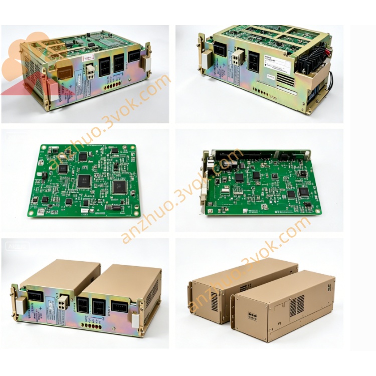
CACR-SR12TB0AF
Description
1. MODEL CODE DEFINITION
2. ELECTRICAL RATINGS & SPECIFICATIONS
Input Power
Main power: 3-phase AC200~230V, tolerance -15%~+10%, 50/60Hz
Control power: Independent single-phase AC200~230V separated input
Output Rating
Continuous rated current: 11.7Arms
Short-time overload: 150% rated for 60s; 300% peak instantaneous overload within 3s
PWM modulation: IGBT sine-wave drive, max output frequency 300Hz
DC bus nominal voltage: DC280~320V; terminals P/BN for external regenerative braking resistor
Environment Spec
Operating temp: 0℃ ~ +55℃; Storage: -20℃ ~ +70℃
Humidity: 5%~80%RH, non-condensation; IP20 protection, cabinet vertical mounting only
Altitude: ≤1000m; derating required over 1000m elevation
Vibration resistance: 10~55Hz, 0.5mm single amplitude
3. MAIN FEATURES
Dual command input:
Analog channel: ±10VDC speed/torque reference input
Pulse channel: Differential line-driver pulse input for position control (A/B/Z pulse)
Speed regulation ratio 1:5000, full load speed fluctuation ≤±0.01%
Built-in digital notch filter to suppress mechanical resonance & low-speed crawl
Full auto-tuning for motor electrical parameters; speed/position loop gain & CN1 I/O fully editable via user constants
Onboard RS422 serial port: parameter upload/download, real-time operation data & fault history reading
Store up to 10 latest fault codes for maintenance inquiry
4. TERMINAL & CONNECTOR DESCRIPTION
R/S/T: 3-phase main AC power input
U/V/W: Servo motor three-phase power output
P / BN: External regenerative resistor connection terminals
CN1: Opto-isolated digital I/O terminal block (Servo ON, Alarm Output, Zero-speed, Fault Reset etc., freely assignable via parameters)
CN2: Encoder dedicated connector for incremental rotary encoder feedback cable
5. PROTECTION FUNCTION LIST
Internal dynamic brake built-in for normal deceleration energy consumption
External regen resistor required for frequent fast stop / heavy cyclic load between P & BN terminals
6. INSTALLATION & WIRING PRECAUTIONS
Mount vertically inside electrical cabinet, reserve ≥50mm upper/lower ventilation space for radiator heat dissipation
Separate power cable & signal cable wiring to avoid electromagnetic interference; shield encoder cable single-end grounding
Cut all AC input power and wait ≥15min for bus capacitor full discharge before opening cover for maintenance to prevent electric shock hazard
7. COMMISSIONING STEP
Confirm power wiring (RST, UVW, control power single-phase) correct before power-up
Connect CN2 encoder cable firmly; no power-on with disconnected encoder
Execute motor auto-tuning via parameter setting after no-load test run
Set I/O definition, loop gain per machine mechanical requirement
No-load jog test → semi-load trial → full-load formal operation
8. REPLACEMENT RULE
Direct replacement available with same full model CACR-SR12TB0AF
CACR-SR12SZxx (robot version) cannot directly substitute due to different internal PCB and firmware
Custom Y-suffix locked firmware models cannot replace this standard AF version
9. TROUBLESHOOTING GUIDE
Overheat Alarm: Radiator dust clog, poor cabinet ventilation or long-term overloaded operation → clean radiator, improve ventilation or reduce load
Encoder Error: Loose CN2 plug, broken encoder wire or damaged motor encoder → check cable & connector
Overvoltage Alarm during fast deceleration: Add external regenerative resistor on P-BN terminals
Overload Alarm: Mechanical jamming or excessive load → inspect transmission structure and reduce load
10. ROUTINE MAINTENANCE
Every startup: Check tightness of power cable, CN1/CN2 connector terminals
Every 3~6 months: Clean cooling fin dust on heat sink
Annual inspection: Check capacitor aging, fan running status and insulation of all cables
Get a Quote