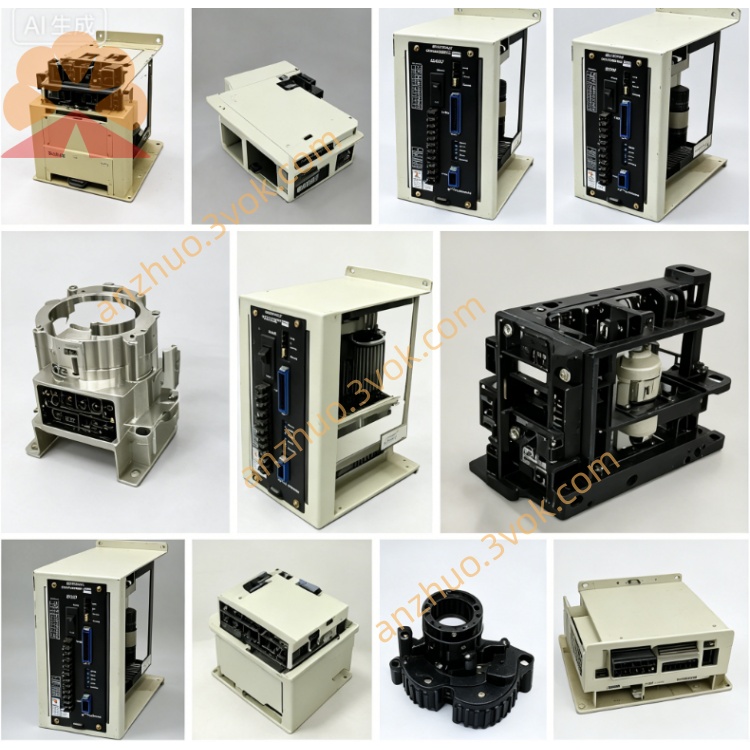
CACR-SR10BC1AF
CACR belongs to Yasnac VS800 full digital AC Servopack series for CNC feed axis motion control.
SR supports three configurable control modes: position, analog speed and torque control via internal parameter setting.
10 corresponds to rated 1.0kW matching servo motor with continuous rated output current 5.3Arms.
BC means revised mainboard layout and standard cabinet housing, different from BB version internal circuit layout;
1 stands for AC200V grade specification for main three-phase power and independent single-phase control power input.
A = only ±10VDC analog speed/torque command input, no built-in differential pulse position command receiving circuit;
F = OEM factory locked firmware version, core servo gain, acceleration/deceleration and I/O definition parameters are pre-set and write-protected, full factory default parameter reset function is disabled by software lock.
Description
1. MODEL CODE DEFINITION
CACR belongs to Yasnac VS800 full digital AC Servopack series for CNC feed axis motion control.SR supports three configurable control modes: position, analog speed and torque control via internal parameter setting.10 corresponds to rated 1.0kW matching servo motor with continuous rated output current 5.3Arms.BC means revised mainboard layout and standard cabinet housing, different from BB version internal circuit layout;1 stands for AC200V grade specification for main three-phase power and independent single-phase control power input.A = only ±10VDC analog speed/torque command input, no built-in differential pulse position command receiving circuit;F = OEM factory locked firmware version, core servo gain, acceleration/deceleration and I/O definition parameters are pre-set and write-protected, full factory default parameter reset function is disabled by software lock.
2. ELECTRICAL SPECIFICATIONS
Main power input: three-phase AC200V~230V, permissible voltage fluctuation -15%~+10%, compatible with 50Hz/60Hz industrial power grid. Independent single-phase AC200V~230V is applied separately for control auxiliary power to isolate main circuit power interference.Continuous rated output current:5.3Arms; 150% rated overload can continuously run for 60 seconds, 300% peak overload is limited within 3 seconds for startup acceleration. DC bus rated working voltage DC280V~DC320V; terminals P and BN are reserved for external regenerative braking resistor connection under frequent heavy-load rapid deceleration working conditions.The drive adopts IGBT sine-wave PWM modulation with maximum output frequency up to 300Hz; encoder resolution parameter is factory preset and locked.
3. ENVIRONMENT & INSTALLATION REQUIREMENT
Operating ambient temperature:0℃ ~ +55℃; storage temperature: -20℃ ~ +70℃. Working relative humidity 5%~80%RH without condensation, protection grade IP20 and vertical upright installation inside electrical cabinet is mandatory.Max allowed installation altitude below 1000m above sea level; derated operation required for installation over 1000m height. Anti-vibration specification:10Hz~55Hz with 0.5mm single amplitude during continuous operation; net weight approx 2.36kg.
4. CONTROL PERFORMANCE FEATURES
Speed adjustment ratio reaches 1:5000, full-load steady speed error controlled within ±0.01%. Built-in digital notch filter suppresses mechanical resonance and low-speed crawl during frequent start-stop movement.Only analog ±10VDC command is available for speed/torque control; position control can be enabled via internal parameter configuration but relevant core position parameters are locked under F firmware.Motor auto-tuning function is partially restricted: complete full auto motor parameter identification is forbidden, only minor auxiliary gain fine-tuning is permitted for slight mechanical matching; CN2 feedback port matches factory specified incremental encoder of corresponding 1.0kW servo motor.
5. TERMINAL AND INTERFACE DESCRIPTION
R/S/T: three-phase main AC power input terminals; U/V/W: three-phase output terminals connected to servo motor main power cable; P/BN: external regenerative braking resistor wiring terminals for surplus regenerative energy consumption during fast deceleration.CN1: opto-isolated I/O terminal block with 8 input channels and 6 relay output channels; I/O signal definition is fixed by F locked factory program, users cannot reassign I/O functions freely through parameter modification.CN2: dedicated connector for incremental encoder feedback cable; onboard RS422 serial port uses Yaskawa proprietary communication protocol, supports real-time data reading and fault code inquiry, core locked parameters cannot be rewritten via communication.
6. PROTECTION FUNCTIONS
Built-in standard dynamic braking circuit handles regular deceleration regenerative energy dissipation; external regenerative resistor installation is required for continuous heavy cutting and repeated emergency stop conditions. High/low speed gain groups are pre-fixed by factory locked parameters.Complete protection includes overcurrent, DC bus overvoltage/undervoltage, drive overheat, encoder disconnection and motor overload protection; the drive automatically saves latest 10 groups of historical fault codes, locked factory preset parameters will not be cleared after power off or fault reset.
7. APPLICATION & REPLACEMENT INSTRUCTION
CACR-SR10BC1AF is factory locked OEM servo driver matched with designated standard 1.0kW incremental servo motor for specific original equipment CNC machine. Cannot directly replace BC1AM open parameter standard model due to parameter lock and fixed I/O definition difference; replacement must adopt identical full part number CACR-SR10BC1AF for plug-and-run.
8. ROUTINE MAINTENANCE INSTRUCTION
Check tightening status of power cable, motor cable and CN2 encoder connector before each startup to avoid poor contact faults. Clean radiator fin dust every 3~6 months to ensure heat dissipation efficiency and prevent overheat alarm.Cut off all AC input power and wait over 15 minutes for full discharge of internal DC bus capacitor before opening drive cover for maintenance to avoid electric shock hazard. Stop continuous running once cabinet inner ambient temperature exceeds 55℃. Arbitrary full parameter factory reset is forbidden to prevent original machine parameter loss.
9. BASIC TROUBLESHOOTING
Overheat alarm is mainly caused by blocked radiator dust, poor cabinet ventilation or long-term overload running. Encoder fault mostly originates from loose CN2 connector or damaged feedback cable.Overvoltage during frequent heavy rapid deceleration can be solved by installing external regenerative resistor between P and BN terminals. Parameter write failure when modifying core parameters is normal F-version write protection instead of drive breakdown. Overload alarm triggers when actual mechanical load exceeds motor rated output, check transmission jamming or reduce processing load.
Get a Quote