CACR-SR10BB1CS-Y114
CACR belongs to Yasnac VS800 full digital AC Servopack series exclusively configured for customized CNC machine tool axis control.
SR supports three switchable control modes including position, speed and torque via internal parameter setup.
10 stands for rated matching motor power 1.0kW, standard continuous output current 5.3Arms.
BB refers to standard universal mainboard and standard cabinet housing without ordinary hardware revision.
Description
1. MODEL CODE DEFINITION
CACR belongs to Yasnac VS800 full digital AC Servopack series exclusively configured for customized CNC machine tool axis control.SR supports three switchable control modes including position, speed and torque via internal parameter setup.10 stands for rated matching motor power 1.0kW, standard continuous output current 5.3Arms.BB refers to standard universal mainboard and standard cabinet housing without ordinary hardware revision.1 represents AC200V class main and control power input specification.C means factory fixed parameter for 2500PPR incremental encoder, only compatible with Yaskawa S-series dedicated servo motor; S denotes dual command input design supporting ±10VDC analog speed signal and differential pulse position signal input.Y114 is special customized OEM suffix: preset fixed machine-specific parameter group locked for designated brand CNC equipment, partial core parameters write-protected by factory custom firmware, cannot restore full factory default freely like standard CS model, I/O signal definition and gain parameters pre-set matching original machine structure.
2. ELECTRICAL SPECIFICATIONS
Main circuit input: three-phase AC200V~230V, allowable voltage fluctuation -15%~+10%, compatible with 50Hz/60Hz industrial power grid. Independent single-phase AC200V~230V supplies separate auxiliary control power to isolate interference from main power loop.Continuous rated output current 5.3Arms; 150% overload sustainable for 60 seconds, 300% peak overload limited within 3 seconds for rapid acceleration. DC bus operating voltage DC280V~DC320V; terminals P and BN reserved for external regenerative braking resistor wiring for frequent heavy-load deceleration working condition.Adopts IGBT sine-wave PWM modulation, maximum output frequency up to 300Hz; encoder feedback parameter permanently fixed at 2500PPR by Y114 customized firmware, unauthorized parameter modification will trigger encoder mismatch alarm directly.
3. ENVIRONMENT & INSTALLATION CONDITIONS
Allowable working ambient temperature range: 0℃ ~ +55℃; storage temperature: -20℃ ~ +70℃. Working environment relative humidity 5%~80%RH without condensation; enclosure protection grade IP20, required vertical upright installation inside electric control cabinet.Max permitted installation altitude below 1000m above sea level; derated running needed for application over 1000m height. Anti-vibration performance: 10Hz~55Hz with 0.5mm single amplitude during continuous operation; net weight approx 2.38kg.
4. CONTROL PERFORMANCE FEATURES
Speed adjustment ratio reaches 1:5000, full-load steady speed error controlled within ±0.01%. Built-in digital notch filter suppresses mechanical resonance and low-speed jitter during frequent start-stop movement.Dual-input S structure allows users to switch command source between analog speed control and pulse position control via available editable parameters; three control modes can also be switched within non-locked parameter range.Auto-tuning function is partially restricted due to Y114 custom lock: complete motor parameter identification is forbidden, only minor gain fine-tuning parameters open for adjustment to protect original machine matching setting; CN2 feedback port exclusively for 2500PPR incremental encoder of matched S-series servo motor.
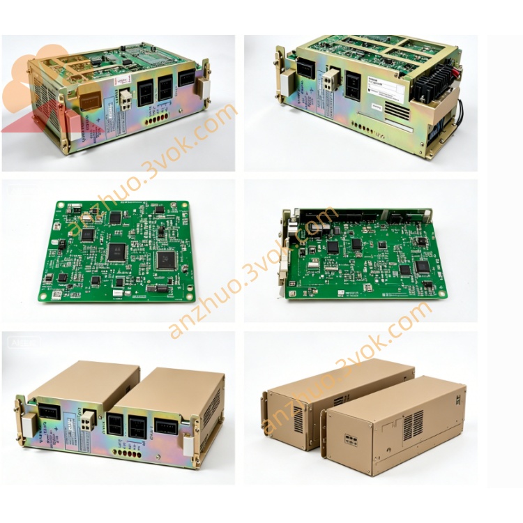
5. TERMINAL AND INTERFACE DESCRIPTION
R/S/T: three-phase main AC power input terminals; U/V/W: three-phase output wiring connecting matched servo motor power cable; P/BN: external regenerative braking resistor connection terminals for regenerative energy consumption during fast deceleration.CN1: opto-coupled isolated I/O terminal block with 8 digital input and 6 relay output channels, I/O logic definition pre-customized by Y114 program for original CNC, partial signal function cannot be redefined freely by parameter modification.CN2: dedicated incremental encoder feedback connector for 2500PPR feedback cable connection; onboard RS422 serial port follows Yaskawa private communication protocol, only supports reading of locked custom parameters, partial important parameters prohibited from online writing.
6. PROTECTION FUNCTIONS
Standard built-in dynamic braking circuit handles regular deceleration regenerative energy dissipation; external brake resistor installation required under continuous heavy cutting and repeated emergency stop working scenario. Independent high/low speed gain groups pre-set by Y114 factory setting for original machine dynamic characteristic matching.Full protection list includes overcurrent, DC bus overvoltage/undervoltage, drive overheat, encoder connection fault, motor overload protection. The drive automatically stores latest ten historical fault codes for maintenance inquiry; locked custom parameters will not be cleared after fault reset or power off operation.
7. APPLICATION & REPLACEMENT INSTRUCTION
CACR-SR10BB1CS-Y114 is OEM customized servo exclusively matched with designated CNC equipment and 1.0kW S-series 2500PPR encoder servo motor. Cannot interchange with ordinary standard CACR-SR10BB1CS model directly, different locked firmware and preset machine parameters will cause abnormal running, positioning deviation or continuous alarm. Replacement must adopt identical full part number CACR-SR10BB1CS-Y114 to guarantee parameter consistency and plug-and-run availability.
8. ROUTINE MAINTENANCE REQUIREMENT
Check tightening status of power cable, motor cable and CN2 encoder connector before every startup to avoid loose wiring induced fault. Clean radiator fin dust every 3~6 months to guarantee heat dissipation efficiency and prevent overheat alarm.Cut off all AC input power and wait more than 15 minutes for internal DC bus capacitor full discharge before opening drive shell for maintenance inspection to prevent electric shock hazard. Stop continuous running once cabinet inner ambient temperature exceeds 55℃.Do not arbitrarily attempt to reset all parameters to factory default; improper full reset will erase Y114 custom preset data and result in machine malfunction.
9. BASIC TROUBLESHOOTING GUIDE
Overheat alarm mainly triggered by blocked radiator dust, poor cabinet ventilation or long-term overloaded running. Encoder fault alarm mostly caused by loose CN2 plug, damaged feedback cable or mistakenly modified fixed 2500PPR encoder parameters under locked firmware restriction.Overvoltage alarm occurs during frequent heavy-load rapid deceleration, solve by installing external regenerative resistor between P and BN terminals. Parameter write failure appears when trying to modify Y114 locked OEM parameters, this is normal customized protection design instead of drive breakdown. Overload alarm activates when actual mechanical load exceeds rated motor output, check transmission jamming or reduce processing load accordingly.
Get a Quote