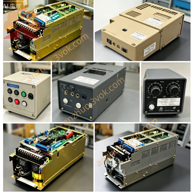
CACR-SR10BB1AF
CACR belongs to Yaskawa classic Yasnac VS800 full digital AC Servopack series specially designed for CNC feed axis and industrial automation positioning equipment.
SR stands for three-control-mode servo drive with position, speed and torque control switchable by modifying internal parameters.
10 indicates rated matching motor power is 1.0kW and the rated continuous output current is 13.0A RMS.
BB means standard universal mainboard PCB design plus regular standard rack housing without special customized hardware modification.
1 represents standard original base firmware edition for 200V power supply class.
A defines command input as only ±10VDC analog signal for speed and torque control instruction without pulse positioning input.
F is OEM factory-locked parameter specification; core application parameters are pre-set and write-protected, full restoration to universal factory default parameters is not available.
Description
1. Model Code Definition
CACR belongs to Yaskawa classic Yasnac VS800 full digital AC Servopack series specially designed for CNC feed axis and industrial automation positioning equipment.SR stands for three-control-mode servo drive with position, speed and torque control switchable by modifying internal parameters.10 indicates rated matching motor power is 1.0kW and the rated continuous output current is 13.0A RMS.BB means standard universal mainboard PCB design plus regular standard rack housing without special customized hardware modification.1 represents standard original base firmware edition for 200V power supply class.A defines command input as only ±10VDC analog signal for speed and torque control instruction without pulse positioning input.F is OEM factory-locked parameter specification; core application parameters are pre-set and write-protected, full restoration to universal factory default parameters is not available.
2. Electrical Specifications
Main circuit power supply is three-phase AC200V~230V with allowable voltage fluctuation ranging from -15% to +10%, applicable for 50Hz and 60Hz industrial power grid.Independent single-phase AC200V~230V provides separate power source for control circuit.Continuous rated output current is 13.0A; 150% overload operation can last for 60 seconds while 300% peak overload is limited within maximum 3 seconds.DC bus working voltage is DC280V~320V, and P/N spare terminals are reserved for external regenerative braking resistor connection under frequent heavy-load deceleration working conditions.The driver applies IGBT sine-wave PWM modulation and adopts dual closed-loop control consisting of current loop and speed loop.
3. Environmental and Mechanical Parameters
Operating ambient temperature ranges from 0℃ to +55℃, storage temperature is between -20℃ and +70℃.Working relative humidity keeps 5%~80%RH without condensation; protection grade is IP20 and the unit requires vertical cabinet rack installation only.Maximum applicable installation altitude is below 1000 meters above sea level, and the servo can withstand vibration of 10~55Hz with 0.5mm single amplitude.Approximate net weight is 2.4kg.
4. Control Performance
Speed adjustment ratio reaches 1:5000 with full-load steady-state speed accuracy controlled within ±0.01%.CN2 feedback connector is exclusively configured for incremental encoder matching corresponding 1.0kW Yaskawa servo motors.Built-in digital notch filter effectively suppresses mechanical resonance and running vibration of mechanical equipment.Automatic motor parameter identification function supports basic motor parameter auto-tuning, but gain, acceleration and deceleration related customized parameters of F version are factory locked and cannot be modified arbitrarily.Three different control modes can be switched by adjusting unlocked available parameters.
5. Interface Configuration
R/S/T terminals connect three-phase main AC power input; U/V/W terminals link three-phase power cables of matched servo motor; P/N terminals are used for external regenerative brake resistor wiring.CN1 is opto-isolated digital I/O terminal block with 8 input channels and 6 relay output channels following fixed OEM signal definition, covering servo enable, forward and reverse overtravel limit, emergency stop, servo ready output and fault alarm output functions.CN2 is dedicated connector for incremental encoder feedback wiring.Onboard RS422 serial port uses Yaskawa proprietary communication protocol to realize parameter reading, writing and real-time running status monitoring.
6. Core Functions and Protection
Position, speed and torque three control modes can be switched freely, and electronic gear ratio function realizes multi-axis synchronous motion for automated production equipment.Internal integrated dynamic braking circuit absorbs most regenerative energy generated during normal deceleration process; external braking resistor is only necessary for heavy-duty frequent emergency stop occasions.Separated high-speed and low-speed gain parameters ensure stable low-speed operation and rapid high-speed dynamic response.Complete protection functions include overcurrent, overvoltage, undervoltage, overheat, encoder fault and motor overload protection. The servo automatically saves latest ten groups of historical fault codes for maintenance inspection.
7. Application & Maintenance Instruction
This OEM locked-parameter servo drive is specially matched with 1.0kW incremental servo motors for designated CNC machine tools and fixed automation production lines; replacement must adopt identical full part number CACR-SR10BB1AF.Check tightness of all power cables, motor wiring and encoder cables to avoid loose connection or short-circuit fault before power-on. Do not alter locked factory preset parameters without mechanical modification of matched equipment.Keep cabinet ventilation smooth during operation, stop long-time continuous running if inner cabinet temperature exceeds 55℃ and avoid frequent short-interval power on and off.Conduct regular maintenance every three to six months including cleaning dust on heatsink and tightening loose terminal screws. Cut off main AC power and wait over 15 minutes for full discharge of internal DC bus capacitor before opening cover for overhaul to prevent electric shock risk.Shut down equipment immediately once continuous fault alarm occurs, then inspect servo motor, connecting cables and mechanical jamming problems before restarting.
8. Basic Troubleshooting
Overheat alarm is generally caused by blocked heatsink, excessively high cabinet ambient temperature or long-term overload operation.Encoder fault alarm mostly results from loose CN2 connector or damaged incremental encoder feedback cable.Overvoltage fault appears during frequent rapid deceleration under heavy load; install external regenerative braking resistor on P/N terminals to solve this issue.
Get a Quote