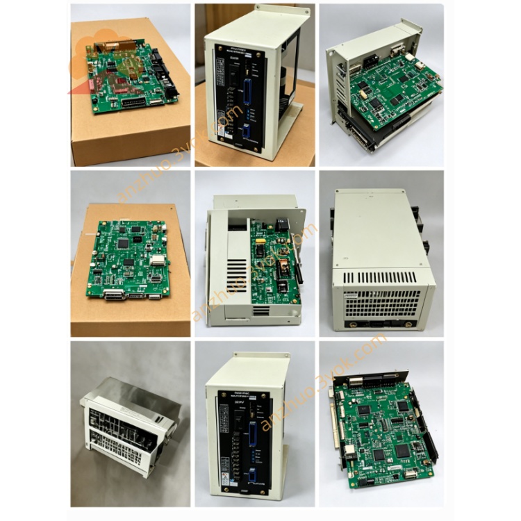
CACR-SR07AC1ER-Y48
CACR belongs to classic Yaskawa Yasnac VS800 full digital AC SERVOPACK servo amplifier series for traditional CNC and automatic machinery. SR stands for general-purpose servo unit with three switchable control modes: position, speed and torque adjustable via internal parameters. 07 means rated matching motor power is 0.7kW with continuous rated output current of 7.6A RMS. A refers to standard universal main control PCB without special base hardware customization. C indicates only ±10VDC analog speed/torque command input is available; differential pulse positioning input is not equipped. 1 represents standard original factory base firmware platform. E specifies CN2 feedback port exclusively for Yaskawa USAREM series incremental encoder motors. R stands for rack-mounted mechanical structure to match R-type USAREM servo motors with dedicated rack installation dimensions. Y48 is exclusive OEM customized code with factory pre-fixed I/O definition and locked dedicated parameter group tuned for specific original equipment; core customized parameters cannot be modified randomly unless matched machine’s mechanical structure is altered.
Description
1. Model Code Definition
CACR belongs to classic Yaskawa Yasnac VS800 full digital AC SERVOPACK servo amplifier series for traditional CNC and automatic machinery. SR stands for general-purpose servo unit with three switchable control modes: position, speed and torque adjustable via internal parameters. 07 means rated matching motor power is 0.7kW with continuous rated output current of 7.6A RMS. A refers to standard universal main control PCB without special base hardware customization. C indicates only ±10VDC analog speed/torque command input is available; differential pulse positioning input is not equipped. 1 represents standard original factory base firmware platform. E specifies CN2 feedback port exclusively for Yaskawa USAREM series incremental encoder motors. R stands for rack-mounted mechanical structure to match R-type USAREM servo motors with dedicated rack installation dimensions. Y48 is exclusive OEM customized code with factory pre-fixed I/O definition and locked dedicated parameter group tuned for specific original equipment; core customized parameters cannot be modified randomly unless matched machine’s mechanical structure is altered.
2. Electrical Specifications
Main circuit power supply is three-phase AC200V~230V with allowable voltage fluctuation range from -15% to +10%, compatible with 50Hz and 60Hz power grid. Independent single-phase AC200~230V terminals are arranged for separated control circuit power input. Rated continuous output current is 7.6A; 300% peak overload can last maximum 3 seconds while 150% overload can run continuously for 60 seconds. DC bus operating voltage is DC280V~320V, and P/N spare terminals are reserved for external regenerative braking resistor connection under frequent heavy-load deceleration conditions. This model adopts pure analog ±10VDC control without digital pulse command channel.
3. Environmental and Mechanical Parameters
Operating ambient temperature ranges from 0℃ to +55℃; storage temperature is between -20℃ and +70℃. Working relative humidity keeps 5%~80%RH without condensation. Protection grade is IP20 and the unit must be vertically mounted on standard cabinet rack following R-type installation requirement. Maximum applicable installation altitude is below 1000 meters above sea level, and the drive resists 10~55Hz vibration with 0.5mm single amplitude. Approximate net weight is 2.0kg.
4. Control Performance
The servo uses IGBT sine-wave PWM dual closed-loop control consisting of speed loop and current loop. Speed adjustment ratio reaches 1:5000 with full-load steady speed accuracy within ±0.01%. CN2 interface only supports USAREM incremental encoder and excludes absolute encoder hardware circuit. Built-in digital notch filter suppresses mechanical resonance and running vibration. Auto motor identification works for basic motor parameter tuning, whereas Y48 customized gain, acceleration and deceleration parameters are factory locked. Three control modes can be switched via modification of non-locked parameters.
5. Interface and Communication Configuration
R/S/T terminals connect three-phase main AC input; U/V/W terminals link servo motor three-phase power cables; P/N terminals are for external regenerative brake resistor wiring. CN1 is opto-isolated 8-input and 6-relay-output I/O block with fixed Y48 OEM signal definition including servo enable, forward/reverse overtravel limit, emergency stop, servo ready output and fault alarm output. CN2 is exclusive connector for USAREM incremental encoder feedback. Onboard RS422 serial port with proprietary Yaskawa protocol enables parameter read/write and real-time operating status monitoring.
6. Core Functions
Three control modes can be switched freely and electronic gear ratio function supports multi-axis synchronous motion for automation equipment. Internal integrated dynamic brake absorbs most regenerative energy during deceleration; external brake resistor is only needed for heavy-load frequent emergency stop occasions. Separated high/low speed gain ensures smooth low-speed running and quick high-speed dynamic response. The drive automatically saves latest 10 historical fault codes for maintenance reference. Y48 preset parameters are optimized for designated OEM machine; unauthorized modification of locked parameters is prohibited.
7. Applicable Scenarios
This Y48 customized rack-type analog servo is specially configured for designated CNC auxiliary feed axes and rack-installed automation equipment matched with 0.7kW USAREM-R incremental servo motors. Replacement must use identical full part number CACR-SR07AC1ER-Y48.
8. Operation and Routine Maintenance Instructions
Check all power cables, encoder wires and I/O wiring for short circuit or loose connection before powering on. Avoid arbitrary change of factory-locked Y48 parameters without equipment mechanical modification. Maintain good cabinet ventilation during operation; stop long-time continuous running if inner cabinet temperature exceeds 55℃ and avoid frequent short-interval power cycling. Perform regular inspection every three to six months: tighten terminal screws, check cable insulation aging and clean dust on heatsink. Cut off main AC supply and wait at least 15 minutes for full DC bus capacitor discharge before internal disassembly to prevent electric shock. Shut down equipment and cut power immediately upon continuous fault alarm, then inspect motor, cables and mechanical jamming before restart.
9. Basic Troubleshooting
Overheat alarm results mainly from clogged heatsink, overhigh cabinet temperature or long-term overload operation. Encoder fault usually comes from loose CN2 connector or damaged incremental feedback cable. Overvoltage occurs during frequent rapid deceleration under heavy load; fit external regenerative resistor between P and N terminals for solution.
Get a Quote