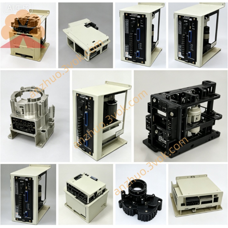
CACR-SR07AC1ER-Y105
CACR represents classic Yaskawa Yasnac VS800 full digital AC SERVOPACK servo amplifier series for traditional CNC and automation machinery. SR refers to universal servo supporting switchable position, speed and torque control modes via internal parameter configuration. 07 stands for rated matching motor power of 0.7kW with rated continuous output current of 7.6A RMS. A means standard universal main control PCB without general custom hardware modification. C defines analog ±10VDC as the only control command input, with no differential digital pulse positioning channel available.
Description
1. Model Code Definition
CACR represents classic Yaskawa Yasnac VS800 full digital AC SERVOPACK servo amplifier series for traditional CNC and automation machinery. SR refers to universal servo supporting switchable position, speed and torque control modes via internal parameter configuration. 07 stands for rated matching motor power of 0.7kW with rated continuous output current of 7.6A RMS. A means standard universal main control PCB without general custom hardware modification. C defines analog ±10VDC as the only control command input, with no differential digital pulse positioning channel available. 1 is standard base firmware platform. E denotes CN2 feedback port designed exclusively for USAREM series incremental encoder motors. R indicates rack-mounted mechanical structure for special installation specification matching R-type servo motors. Y105 is dedicated OEM customized suffix with factory pre-fixed I/O logic and locked optimized parameters for designated original equipment; core customized parameters are prohibited from random revision without mechanical structure change of matched machine.
2. Electrical Specifications
Main circuit power input is three-phase AC200V~230V with permissible voltage fluctuation of -15%~+10%, compatible with 50Hz and 60Hz power supply. Independent single-phase AC200~230V terminals are reserved for separated control circuit power supply. Continuous rated output current is 7.6A; 300% peak overload can last maximum 3 seconds and 150% overload can sustain continuous operation for 60 seconds. Nominal DC bus voltage ranges DC280V~320V, and P/N spare terminals are reserved for external regenerative braking resistor connection under frequent heavy-load deceleration working conditions. Only ±10VDC analog speed or torque command is supported for this model without pulse input function.
3. Environmental and Mechanical Parameters
Operating ambient temperature ranges from 0℃ to +55℃, storage temperature covers -20℃~+70℃. Working relative humidity keeps between 5% and 80%RH without condensation. Protection grade is IP20 and the unit must be installed inside closed electrical cabinet following rack mounting requirement of R specification. Maximum applicable installation altitude is below 1000 meters above sea level, and the drive can withstand 10~55Hz vibration with 0.5mm single amplitude. Net weight is approximately 2.0kg.
4. Control Performance
The servo adopts IGBT sine-wave PWM dual closed-loop control including speed loop and current loop. Speed adjustable ratio reaches 1:5000 with full-load steady-state speed precision within ±0.01%. CN2 interface only matches USAREM incremental encoder without absolute encoder compatible circuit. Built-in digital notch filter suppresses mechanical resonance and running vibration. Automatic motor parameter identification is available for basic motor parameter tuning while Y105 OEM customized gain and acceleration/deceleration parameters are pre-locked at factory setting. Three control modes can be switched by modifying available non-locked parameters.
5. Interface and Communication Configuration
R/S/T terminals connect three-phase main AC power input; U/V/W terminals link three-phase power wiring of matched servo motor; P/N spare terminals are for external regenerative brake resistor wiring. CN1 is opto-isolated digital I/O terminal block with 8 input channels and 6 relay output channels following fixed Y105 customized pin definition, covering servo enable, forward/reverse overtravel limit, emergency stop, servo ready output and fault alarm output functions. CN2 is exclusive connector for USAREM incremental encoder feedback wiring. Onboard RS422 serial port with Yaskawa proprietary communication protocol is used for parameter reading, writing and real-time running status monitoring.
6. Core Functions
Three control modes can be flexibly switched and electronic gear ratio setting supports multi-axis synchronous linkage for automation equipment. Internal integrated dynamic braking circuit absorbs most regenerative energy generated during deceleration; external brake resistor is only needed for heavy-duty frequent emergency stop scenarios. Segmented high and low speed gain ensures stable low-speed running and fast high-speed dynamic response. The drive automatically stores latest 10 groups of historical fault codes for maintenance check. Factory preset Y105 parameters are calibrated for specific OEM machine and arbitrary parameter modification is not recommended.
7. Applicable Scenarios
This Y105 customized rack-mounted analog servo drive is exclusively tailored for designated 0.7kW USAREM-R motor equipped CNC feed axis and special rack-type automated production equipment. Equipment maintenance replacement must select identical full part number CACR-SR07AC1ER-Y105.
8. Operation and Routine Maintenance Instructions
Before power-on, inspect all power cables, encoder wires and I/O signal wiring to exclude short circuit, loose terminals and wrong connection risks. Avoid random alteration of locked Y105 factory preset parameters without mechanical modification of matched equipment. Keep cabinet ventilation unobstructed during operation, prohibit long-time continuous running when inner cabinet temperature exceeds 55℃ and prevent frequent repeated power on/off within short intervals. Conduct periodic maintenance every three to six months: tighten all terminal screws, inspect cable insulation aging and clean dust accumulated on drive heat sink. Cut off main AC power and wait no less than 15 minutes for full discharge of internal DC bus capacitor before any internal disassembly maintenance to avoid electric shock hazard. Stop equipment and cut off power immediately upon continuous fault alarm, then inspect servo motor, connecting cables and mechanical jamming before restarting operation.
9. Basic Troubleshooting
Overheat alarm is commonly caused by blocked heat sink, excessive cabinet ambient temperature or long-term overload operation. Encoder fault alarm mostly originates from loose CN2 connector or damaged incremental encoder feedback cable. Overvoltage fault appears under frequent rapid deceleration with heavy load; install external regenerative braking resistor on P/N terminals to solve the issue.
Get a Quote