CACR-SR03SB1BF
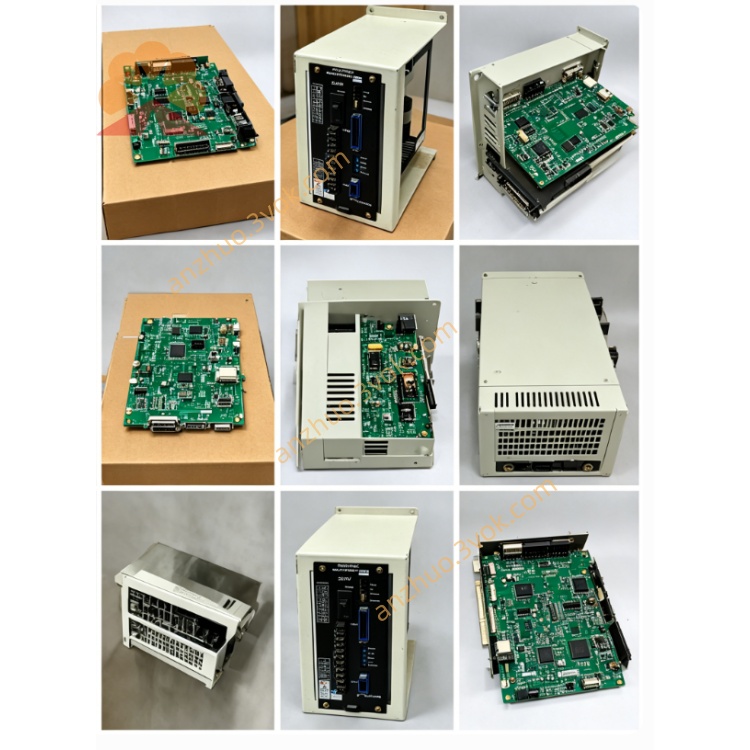
CACR-SR03SB1BF is a 0.3kW original Yaskawa AC Servopack from the classic discontinued CACR-SR series, designed to cooperate with Yasnac VS-800 CNC system for feed-axis control on conventional CNC lathes and small machining centers. It is mainly used as replacement spare part for maintenance of old equipment and matched with Yaskawa USAF series 300W incremental encoder servo motors. This is a standard universal version without factory-locked OEM parameters, allowing regular parameter adjustment for commissioning.
Description
1. Product Overview
CACR-SR03SB1BF is a 0.3kW original Yaskawa AC Servopack from the classic discontinued CACR-SR series, designed to cooperate with Yasnac VS-800 CNC system for feed-axis control on conventional CNC lathes and small machining centers. It is mainly used as replacement spare part for maintenance of old equipment and matched with Yaskawa USAF series 300W incremental encoder servo motors. This is a standard universal version without factory-locked OEM parameters, allowing regular parameter adjustment for commissioning.
2. Model Code Definition
CACR is the general series designation for Yaskawa AC servo amplifier. SR stands for versatile control platform supporting speed, position and torque control via internal parameter configuration. 03 means rated output power of 0.3kW. SB refers to 200V-grade dedicated main power board with unique internal circuit design different from BB, BE and BY types. 1BF represents B-type control board paired with F-standard incremental encoder interface circuit exclusively for USAF servo motors.
3. Electrical Specifications
Main power input is three-phase AC 200V~230V with +10%/-15% voltage tolerance at 50Hz or 60Hz. The control circuit adopts independent single-phase AC 200~230V power supply. Rated continuous output current is 3.0Arms and peak transient overload current reaches 8.5Arms for short-time acceleration and deceleration. Operating ambient temperature ranges from 0℃ to 55℃, storage temperature from -20℃ to 85℃, and working humidity shall not exceed 80%RH without condensation. With IP20 protection grade, the unit can only be installed inside control cabinet and should avoid environments with corrosive gas, heavy dust and oil mist. IGBT sine-wave PWM drive technology is applied for smooth motor operation.
4. Main Control Features
Three optional control modes including speed, position and torque control are available. The drive receives ±10VDC analog speed and position command signal from Yasnac CNC controller, and most internal parameters are factory default and freely adjustable without fixed OEM firmware restriction. Optimized anti-interference circuit on control board ensures stable incremental encoder feedback signal transmission under complicated industrial electromagnetic conditions.Complete protection functions cover overcurrent, overvoltage, undervoltage, overheat, regenerative circuit failure, encoder signal loss and CPU abnormal protection. A single seven-segment digital display on front panel shows real-time operating status and numeric fault codes; terminals P and N are reserved for external regenerative braking resistor connection.
5. Wiring Instruction
R, S, T terminals connect three-phase input power source; U, V, W terminals link three-phase power cables of matched USAF servo motor; PE terminal must be reliably connected to protective ground following local electrical safety regulations; P and N terminals are used for external brake resistor wiring.Control terminal block receives analog command from CNC system, equipped with digital input for servo enable and fault reset signals, and dry-contact relay output provides external fault alarm feedback. A dedicated round aviation connector is configured for incremental encoder wiring complying with BF standard pin definition.
6. Installation and Commissioning
Mount the servo vertically inside electrical cabinet and reserve enough top and bottom clearance for heat dissipation, keeping away from heat-generating components such as transformers and contactors. Inspect all wiring thoroughly before power-on to prevent short circuit. No mandatory fixed parameter setting is required during regular replacement, and parameter tuning can be done on site as needed. Complete no-load jog test to confirm motor rotation direction and running stability before connecting mechanical load.
7. Maintenance & Troubleshooting
Cut off all input power and wait more than 10 minutes for residual high voltage discharge of internal capacitors before any maintenance work to avoid electric shock. Clean cooling vents and tighten terminal screws every quarter regularly. Once alarm code appears, check sequentially input power fluctuation, motor mechanical jamming, loose encoder wiring and insufficient cabinet heat dissipation; do not restart repeatedly until faults are fully eliminated.
Get a Quote