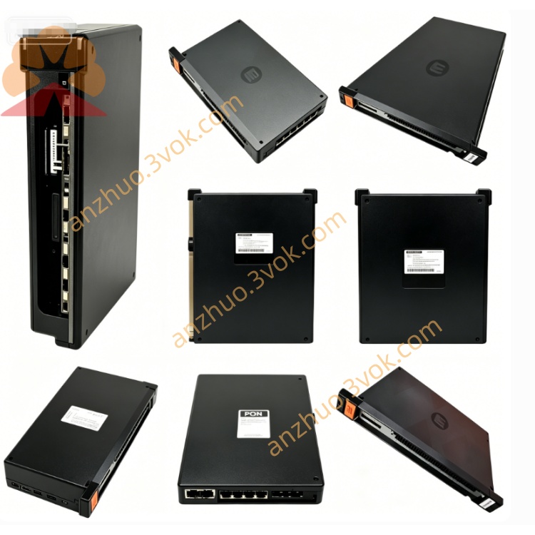
Reliance 57C422B revised 2-axis servo motion control module
Description
Product Brief Introduction
Model Definition
57C: Reliance’s 57C series rack-mounted modular control platform for AutoMax systems, focused on motion and I/O modules.
422: Core identifier for the 2-axis servo motion control module, distinguishing it from other 57C series modules (e.g., 57C421 mainboard).
B: Hardware revision suffix, indicating the second production revision with upgraded components, improved thermal resistance, and enhanced fault detection circuitry compared to the original 57C422.
Technical Specifications
Processor: 80186-compatible microprocessor with 4K×15 dual-port memory for high-speed data exchange.
Power Supply: 5V DC from rack backplane; auxiliary ±12V/±15V for analog circuits, 650mA typical current draw.
Axis Configuration: 2 independent servo axes with dedicated control loops.
Encoder Interface: Differential TTL, 5V logic, 250kHz maximum frequency per channel, 4.5mA max input current.
Control Loop Performance: 1.25ms update rate for position/velocity loops; 50µs transport delay for real-time responsiveness.
Registration Input: 15–24V DC electronic signal for position latching.
Operating Conditions: 0°C to 60°C (operating); -20°C to 70°C (storage); 5%–95% non-condensing humidity.
Protection: Onboard hardware watchdog with relay interlock for drive enable circuitry; overvoltage/overcurrent protection per axis.
Indicators: 8 LEDs per axis (HOME, FAULT, ENABLE, etc.) plus STAT and OK LEDs for real-time status monitoring.
Interface and Communication Configuration
Backplane Interface: Gold finger connection to AutoMax Multibus backplane, using proprietary Reliance protocol for high-speed data exchange with host processors (AutoMax/DCS 5000) and other modules.
External I/O: Two 37-pin D-Sub connectors on the front panel for servo drive control signals and differential encoder feedback.
Auxiliary Ports: Two RS-232 ports (X/Y axes) for local diagnostics and configuration.
Network Connectivity: No standalone fieldbus ports; relies on host system or 57C series communication modules for upper-layer network access.
Core Functions
2-Axis Closed-Loop Control: Executes point-to-point positioning, velocity, and acceleration control with high precision for two independent axes.
Electronic Gearing/Camming: Replaces mechanical gears and cams with electronic synchronization, reducing wear, backlash, and setup time.
High-Speed Encoder Processing: Reads differential TTL encoder signals up to 250kHz for accurate position tracking.
Drive Interface Management: Outputs velocity/current commands to AC/DC servo amplifiers and monitors drive fault signals.
System Monitoring & Protection: Watchdog timer monitors CPU health; interlock relay disables drives on faults; axis-specific fault detection and alarm upload.
Multi-Axis Synchronization: Connects with other 57C422B modules for coordinated motion across multiple axes.
Application Scenarios
Legacy System Retrofits: Direct replacement for original 57C422 modules in aging AutoMax-based production lines, restoring motion control performance.
Industrial Motion Automation: CNC machinery, robotics, and automated assembly lines requiring precise 2-axis control.
Material Handling & Packaging: Conveyors, winding equipment, and packaging machines needing synchronized axis motion.
Metalworking & Printing: Machine tools, press brakes, laser cutters, and printing roller lines requiring high-speed, accurate positioning.
Operation and Maintenance Instructions
Installation: Power off the rack before insertion; align with chassis rails, fully seat backplane gold fingers, and secure with faceplate screws to ensure stable contact.
Wiring: Use shielded twisted-pair cables for encoder and drive connections; separate signal cables from power cables to minimize EMI.
Routine Maintenance: Every 3–6 months, power down the system and clean the module surface and rack vents with dry compressed air to remove dust; avoid liquid cleaners.
Fault Diagnosis: Check axis LEDs (X FAULT, Y FAULT) for status; verify backplane connections if communication errors occur; use RS-232 ports for local diagnostics.
Replacement: Replace with a 57C422B (revision B) module if persistent faults occur; update system parameters to match the new module’s configuration.
Storage: Keep spare modules in a dry, temperature-controlled environment away from corrosive gases and strong electromagnetic fields.
Modification: Do not alter onboard circuits or components without factory authorization, as this voids warranty and may cause system instability.
Get a Quote