JANCD-MIO03
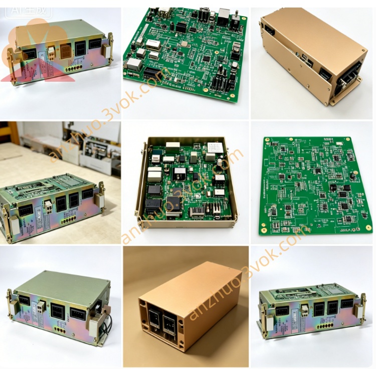
JANCD-MIO03 is a digital input and output expansion board specially designed for Yaskawa robot controllers including DX100, DX200 and YRC1000 series. This board is configured with 16 digital input channels and 16 digital output channels. The input supports 24 VDC power supply and can switch between sink mode and source mode. Each output channel adopts 24 VDC power supply, with the maximum load current of 0.5 ampere. The standard version of this board is REV.01, and its overall weight is approximately 1.0 kilogram.
Description
1. Overview
JANCD-MIO03 is a digital input and output expansion board specially designed for Yaskawa robot controllers including DX100, DX200 and YRC1000 series. This board is configured with 16 digital input channels and 16 digital output channels. The input supports 24 VDC power supply and can switch between sink mode and source mode. Each output channel adopts 24 VDC power supply, with the maximum load current of 0.5 ampere. The standard version of this board is REV.01, and its overall weight is approximately 1.0 kilogram.
2. Technical Specifications
This product is a dedicated I/O expansion board for robot systems. All input channels work under 24 VDC voltage, and the typical operating current for each input is 10 milliamperes. All output channels adopt 24 VDC power supply, and each single channel has a maximum output current of 0.5 ampere. The external working power supply is 24 VDC with a tolerance range of plus or minus 10 percent, and the maximum total working current of the board is 1.5 ampere. The applicable ambient temperature ranges from 0 degree Celsius to 55 degree Celsius. The board is installed inside the robot controller, compatible with standard slot installation and DIN rail installation methods.
3. Connector Definition
3.1 CN303 Power and Common Terminal
Pin 1 is connected to external 24 VDC positive power. Pin 2 is connected to power ground. Pin 3 serves as the common terminal for all input signals. Pin 4 serves as the common terminal for all output signals.
3.2 Input Terminals CN306, CN308, CN309
These terminals correspond to 16 input channels from channel 1 to channel 16. When working in sink mode, connect the input common terminal to 24 VDC positive. The input signal will be triggered to ON state when the signal terminal is connected to 0 V. When working in source mode, connect the input common terminal to 0 V. The input signal will be triggered to ON state when the signal terminal is connected to 24 VDC positive.
3.3 Output Terminal CN307
This terminal corresponds to 16 output channels from channel 1 to channel 16. For PNP source output mode, connect the output common terminal to 0 V. The output terminal will output 24 VDC positive when the signal is ON. For NPN sink output mode, connect the output common terminal to 24 VDC positive. The output terminal will be connected to 0 V when the signal is ON. The maximum current of each output channel shall not exceed 0.5 ampere, and the total output current of all channels shall not exceed 1.5 ampere.
4. Installation Steps
Cut off the power supply of the robot controller completely before any installation operation. Insert JANCD-MIO03 into the vacant I/O slot inside the controller, and fasten the board with fixing screws. Connect the CN303 terminal to external 24 VDC power supply, which is recommended for use when connecting high-current loads. Complete the wiring of input and output signals on CN306, CN307, CN308 and CN309 according to on-site requirements. After all wiring and installation are finished, restore the power supply of the controller, and complete the I/O parameter configuration through the robot teach pendant.
5. Default I/O Address Allocation
The 16 input channels correspond to the address range from 20010 to 20027 by default. The 16 output channels correspond to the address range from 30010 to 30027 by default. To check and modify I/O related settings, enter the system menu of the teach pendant, select the I/O option, and open the module setting page for configuration.
6. Safety Instructions and Daily Maintenance
Always disconnect the power supply before wiring, disassembly and routine maintenance to avoid electric shock and equipment damage. Do not use the product beyond the rated current parameters, so as to prevent the circuit board and peripheral equipment from burning out. It is recommended to use shielded cables for signal wiring to enhance anti-interference ability and ensure stable signal transmission. Keep the ventilation space around the board unobstructed, and clean the accumulated dust regularly to maintain normal heat dissipation.
7. Access to Official Full Manual
You can obtain the complete original English version of the manual on Yaskawa e-mechatronics official website. Register and log in to the website, enter JANCD-MIO03 in the search box, and you can download the official supporting instruction manual.
Get a Quote