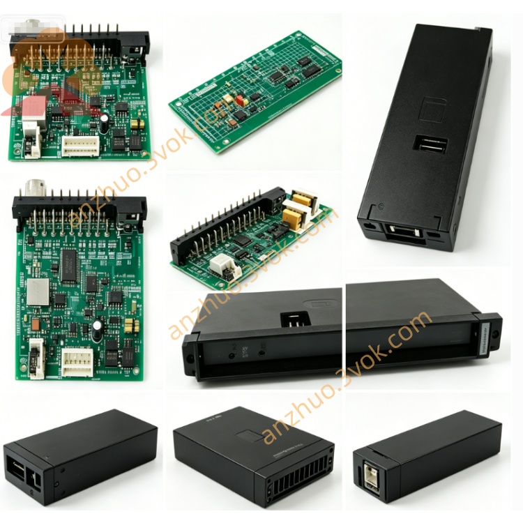
RELIANCE 57552-4 high-performance Universal Drive Controller (UDC)
Description
Product Overview
Model Definition
Technical Parameters
Power Supply: +5VDC (logic) and +24VDC (I/O network) from rack backplane.
Control Capacity: Controls 1 or 2 AC/DC drives; up to 10 modules per rack (20 drives total).
Memory: 256KB non‑volatile flash, 512KB SRAM, 4KB dual‑port SRAM.
Indicators: LEDs for CARD OK, OS OK, COMM A/B OK, DRV A/B FLT.
Operating Temperature: 0°C to +60°C; industrial grade for harsh conditions.
Mounting: Single‑slot AutoMax rack mount; metal enclosure.
Protection: Overvoltage, overcurrent, short‑circuit, and drive fault detection.
Interface and Communication Configuration
Backplane Interface: Multibus connector for high‑speed data exchange with AutoMax processors.
Drive Communication: Dual fiber‑optic links (COMM A/B) for isolated, noise‑immune drive connections.
Front Panel: Status LEDs, test ports, and diagnostic switches for on‑site troubleshooting.
Configuration: Software‑configured via AutoMax tools; no user‑set switches.
Core Functions
Executes complex motion control algorithms for speed, torque, and position regulation on 1–2 drives.
Enables high‑speed data exchange with system processors via dual‑port memory and fiber links.
Retains programs/parameters in non‑volatile flash to prevent data loss during power outages.
Provides real‑time monitoring and fault reporting for drives, communication, and internal circuits.
Supports multi‑drive coordination and synchronized motion in automated production lines.
Application Scenarios
Heavy‑duty industrial automation using AutoMax DCS/PLC platforms.
Motion control in steel, pulp and paper, material handling, and manufacturing.
Centralized drive control cabinets and remote I/O racks requiring high‑precision coordination.
System upgrades or retrofits replacing legacy drive controllers in existing AutoMax installations.
Operation and Maintenance Instructions
Installation: Power off the rack before inserting into a single AutoMax slot; ensure secure backplane connection.
Wiring: Connect fiber‑optic cables to COMM A/B; verify drive wiring matches software configuration.
Operation: Maintain 0°C to +60°C ambient temperature; ensure adequate ventilation and avoid dust/moisture/corrosive gases.
Maintenance: Inspect fiber cables for damage; check LED status regularly; clean module surface periodically.
Troubleshooting: If DRV FLT LED is on, power off and inspect drive wiring; use AutoMax diagnostic software for fault analysis.
Replacement: Replace only with the same model (57552‑4) or compatible revision to ensure system compatibility.
Get a Quote