RELIANCE 57552-1 ( 57C552-1)universal drive controller module
Description
Product Overview
Model Definition
Technical Parameters
Power Supply: +5VDC (logic), +24VDC (I/O network) from rack backplane.
Control Capacity: Controls 1 or 2 AC/DC drives; up to 10 modules per AutoMax rack.
Memory: Non‑volatile flash memory for program/data storage; dual‑port memory for backplane data exchange.
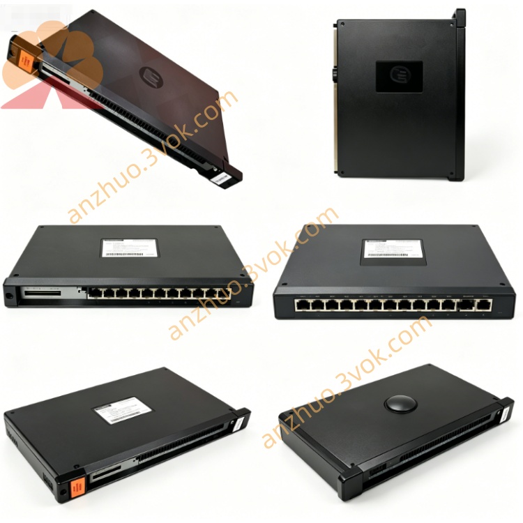
Indicators: LEDs for CARD OK, OS OK, COMM A OK, DRV A FLT, COMM B OK, DRV B FLT.
Operating Temperature: 0°C to +60°C.
Mounting: Single‑slot AutoMax rack mount; metal enclosure with mounting tabs.
Protection: Overvoltage, overcurrent, short‑circuit protection; drive fault detection and reporting.
Interface and Communication Configuration
Backplane Interface: Multi‑Bus backplane connector for high‑speed data exchange with AutoMax processors.
Drive Communication: Dual fiber‑optic links (COMM A/COMM B) for isolated, noise‑immune drive communication.
Front Panel: Meter ports, test switches, and status LEDs for on‑site diagnostics.
No User Config Switches: Configuration via system software; status monitored through AutoMax diagnostic tools.
Core Functions
Executes high‑precision control for 1–2 AC/DC drives, including speed, torque, and position regulation.
Facilitates data exchange with AutoMax processors via dual‑port memory and fiber‑optic links.
Stores control programs and parameters in non‑volatile flash memory to prevent data loss during power outages.
Provides real‑time fault monitoring and reporting for drives and communication channels.
Supports coordinated motion control across multiple drives in automation systems.
Application Scenarios
Industrial automation and process control systems using AutoMax DCS/PLC platforms.
Motion control applications in manufacturing, steel, pulp and paper, and material handling.
Centralized drive control cabinets and remote I/O racks requiring reliable, high‑precision drive coordination.
Retrofit projects replacing legacy drive controllers in existing AutoMax systems.
Operation and Maintenance Instructions
Installation: Power off the rack before inserting the module into a single AutoMax slot; ensure proper backplane connection.
Wiring: Connect fiber‑optic cables to COMM A/COMM B ports; verify drive connections match module configuration.
Operation: Maintain adequate ventilation (0°C to +60°C); avoid dust, moisture, and corrosive gases.
Maintenance: Regularly inspect fiber‑optic cables for damage; check LED status indicators for faults.
Troubleshooting: If DRV FLT LED illuminates, power off and inspect drive wiring/connections; use diagnostic software for fault analysis.
Replacement: Replace only with the same model (57552‑1) or compatible revision to ensure system compatibility.
Get a Quote