D0148MU-AD0148MP
Description
# 1. Core Product Parameters
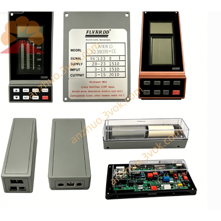
Model: D0148MU, AD0148MP, 8-channel Isolated Digital Output Module of Foxboro I/A Series 100
Number of Channels: 8 independent isolated digital output channels
Output Type: 24VDC transistor output, sink/source type configurable
Operating Voltage: 20.4~28.8VDC (Rated 24VDC)
Single Channel Load Current: Max 0.5A per channel
Total Module Output Current: Max 4A
Electrical Isolation: 250VAC insulation isolation between channels and between channels and ground
Self-diagnosis Function: Supports detection and alarm of short circuit, open circuit and overcurrent faults
Power Supply Mode: Powered by DCS system backplane 24VDC ±10%
Module Power Consumption: ≤4W
Operating Ambient Temperature: 0℃~+55℃
Storage Temperature: -40℃~+85℃
Ambient Humidity: 5%~95% RH, non-condensing
Installation Method: Single-slot backplane installation for standard 19-inch cabinet
Features: Supports cabinet hot swapping and online replacement without shutdown
## II. Key Notes for Installation and Wiring
The module shall be vertically mounted on the dedicated baseplate of the I/A 100 series, with a heat dissipation clearance of no less than 50mm reserved at the top and bottom to avoid high temperature in enclosed spaces.
Shielded twisted-pair cables with wire gauge of 18~22AWG shall be used for on-site wiring; the shield layer shall be reliably grounded at one single end, and the maximum wiring distance shall not exceed 300m.
Signal cables shall be routed separately from power high-voltage cables and kept away from inverters and high-power contactors to avoid electromagnetic interference.
Strictly distinguish the positive and negative output poles to prevent reverse connection; freewheeling diodes must be installed when driving relays and solenoid valves to suppress reverse high voltage and avoid module damage.
Tighten all wiring terminals firmly to eliminate poor contact and looseness, preventing on-site misoperation or signal jitter.
Wear an anti-static wristband during installation and plugging/unplugging operations; direct contact with the gold fingers and electronic components of the circuit board is prohibited.
## III. Key Notes for Operation and Maintenance
Before power-on, confirm normal power supply of the backplane and no short circuit or wrong connection of external lines; switch on the power only after all checks are correct.
### Panel Indicator Status
- PWR green light always on: Power supply normal
- RUN green light flashing: Module operation and communication normal
- FAULT red light always on / flashing: Channel fault, overcurrent, short circuit or abnormal communication
Dual module redundant pairing is supported with bumpless switching time less than 50ms during faults, applicable to critical process interlock loops.
Frequent live plugging and unplugging is prohibited during normal operation; hot swapping is only allowed for faulty replacement.
Regular inspection: Clean cabinet dust, check terminal tightness and integrity of shield grounding.
This series of modules has been discontinued with no original new parts or maintenance accessories available. Replace the entire module with spare parts directly in case of failure; unauthorized disassembly and repair are forbidden.
## IV. Compatibility Notes
- **Model Compatibility**: D0148MU and AD0148MP are fully interchangeable with identical hardware functions, pins and parameters.
- **System Compatibility**: Compatible with Foxboro I/A 100 series systems and legacy controller baseplates such as CP10, CP30 and CP60.
- **Equivalent Replacement in Same Series**: FBM08 can be used as a direct substitute with identical specifications, points and functions.
- **Upgraded Compatible Replacement**: FBM238 digital output module of I/A 200 series can be adopted to adapt to the hardware architecture of new systems.
- **Spare Parts Compatibility**: Only second-hand/refurbished spare parts are available on the market, and the two models can serve as mutual standby spare parts.
Get a Quote