
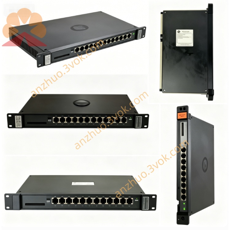
Reliance Electric100C64(Industrial control board card)
Description
Product Introduction
100C64 is a dedicated control board card for the MaxPak/DC Drive series of DC drives under Reliance Electric (now part of ABB/Baldor). As the core signal processing unit of the drive system, it is responsible for speed closed-loop control, trigger pulse generation, fault diagnosis, and I/O signal interaction. It is compatible with the 086466 series rectifier bridge and is widely used in industrial DC motor speed control scenarios.
Model Interpretation
100: Series code, representing the Reliance standard industrial control board platform
C: Control Board identifier
64: Version/functional specification code, corresponding to 64-point I/O configuration and a specific firmware version.
Technical Parameters
Power Supply: 24VDC ±10%, supplied by the drive auxiliary power supply
Control Output: 6 SCR trigger pulses (compatible with three-phase rectifier bridge)
I/O Configuration: 32 digital inputs, 32 digital outputs, 4 analog inputs (0-10V/4-20mA), 2 analog outputs
Control Accuracy: Speed closed-loop accuracy ±0.1%, response time ≤ 10ms
Protection Functions: Overcurrent, overvoltage, overheat, demagnetization, phase loss detection and protection
Environmental Parameters: Operating temperature 0℃~+60℃, storage temperature - 40℃~+85℃, humidity 5%-95% (no condensation)
Installation: Standard rails / backplane installation, compatible with MaxPak drive machine cabinet.
Interface and Communication Configuration
Power Supply Interface: 24VDC positive and negative terminals, grounding terminal
Power Output Interface: 6 SCR trigger output terminals (corresponding to 6 thyristors of the rectifier bridge)
I/O Interface: Digital input/output terminal block, analog input/output terminal block
Communication Interface: RS-232/RS-485 serial ports (parameter configuration and communication with the upper computer)
Diagnostic Interface: Fault indicator lights (power, operation, overcurrent, overheat), test points. Core function
Speed closed-loop control: Receives speed encoder signals, adjusts the trigger angle of the SCR through the PID algorithm to achieve high-precision speed regulation of the DC motor.
Trigger pulse generation: Outputs 6 synchronous trigger pulses to control the conduction sequence of the three-phase SCR rectifier bridge, realizing AC-DC power conversion.
Fault monitoring and protection: Real-time monitors parameters such as current, voltage, and temperature. In case of a fault, immediately blocks the trigger pulses and outputs an alarm signal to protect the driver and the motor.
I/O signal interaction: Receives external start/stop, forward/reverse command instructions, and outputs operating status and fault signals, compatible with PLC and on-site sensors.
Parameter configuration and storage: Configures parameters such as speed, current, and protection thresholds through the serial port, and automatically saves data upon power loss. Applicable scenarios
Reliance MaxPak/MaxPak Plus series DC drivers, compatible with rectifier bridges such as 086466-60R/74RC.
Industrial DC motor speed control: 20-500HP DC motors, suitable for heavy-load scenarios in industries like steel, papermaking, mining, and cement.
Equipment requiring high-precision speed control: such as extruders, winding machines, cranes, conveyors, etc.
Harsh industrial environments: dusty, vibrating, and highly susceptible to electromagnetic interference production sites.
Operation and maintenance instructions Use
Installation: Fix the board card on the standard guide rails of the drive cabinet to ensure good heat dissipation and no obstructions.
Wiring: Connect the 24VDC power supply, SCR trigger line, I/O signal line and communication line according to the terminal definitions. Tighten the terminals to avoid loosening.
Configuration: Connect to the upper computer via serial port, set motor parameters, speed closed-loop parameters, and protection thresholds, and save the configuration.
Operation: Before powering on, check that the wiring is correct. Start the drive, control the motor start/stop and speed adjustment through the panel or the upper computer, and observe the operation status and indicator lights. Maintenance
Daily inspection: Check the status of the indicator lights on the board every week to ensure there are no fault alarms; inspect whether the terminals are loose or overheating.
Cleaning: Blow away the dust on the surface of the board with dry compressed air every quarter to prevent dust accumulation from affecting heat dissipation and insulation.
Firmware upgrade: If necessary, upgrade the firmware via the serial port. Back up parameters before upgrading to ensure stable power supply.
Storage: Store the spare board in a dry and cool environment to avoid static electricity. Package it in an anti-static bag.
Maintenance: Faulty boards need to be repaired by professionals. Do not disassemble them yourself. After maintenance, reconfigure the parameters and test.
Get a Quote