
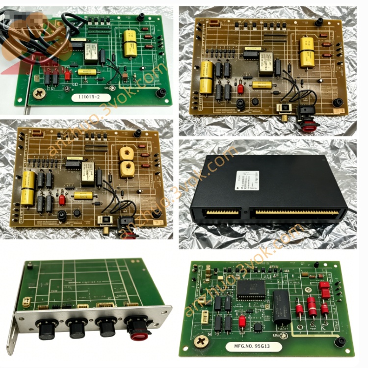
Reliance 119050-8R (PC Speed Control Module)
Description
Product Introduction
Model Definition
119050: Base part number, identifying a Reliance PC Speed Control Module for industrial drive/control systems.
8R: Revision 8, denoting the 8th hardware revision of the board; revisions reflect component upgrades, layout optimizations, compatibility enhancements, or minor functional improvements to address field issues.
Technical Specifications
Manufacturer: Reliance Electric (ABB/Baldor-Reliance)
Product Type: PC Speed Control Module (Plug-in Drive Control Board)
Compatible Systems: Reliance AutoMax PLC, GV3000/SE AC Drives, and legacy DC drive systems
Core Function: Precision motor speed regulation, closed-loop feedback control, signal amplification, and drive coordination
Input Signals: Accepts analog speed reference signals (0–10VDC/4–20mA), encoder feedback, and system enable/disable signals
Output Signals: Provides conditioned speed control signals to drive regulators, fault status outputs, and speed feedback signals to the controller
Power Requirements: Powered via backplane or dedicated 115/230VAC auxiliary power from the drive chassis
Operating Temperature: 0°C to +45°C
Humidity: 5%–95% RH (non-condensing)
Mounting: Standard industrial card edge connector, fits dedicated slots in Reliance drive/controller racks
Dimensions: Standard Reliance module form factor (length × width × height)
Weight: Approximately 0.23 kg
Status: Obsolete (discontinued by Rockwell Automation in 2005)
Interface and Communication Configuration
Host Interface: Connects directly to the drive/controller backplane via a gold-plated edge connector, enabling high-speed, noise-immune data exchange between the speed control module and the system CPU/regulator.
Analog Interfaces: Isolated analog input terminals for speed reference (0–10VDC/4–20mA) and encoder feedback; isolated analog output terminals for drive speed command and fault indication.
Digital Interfaces: Dry-contact digital input for system enable/reset; digital output for fault alarm and speed-lock confirmation.
Network Compatibility: Integrates with AutoMax R-Net and DeviceNet networks via the host controller, supporting remote speed setpoint adjustment, diagnostic data exchange, and system coordination in distributed control systems.
No External Communication Ports: All primary communication occurs via the backplane; network access is routed through the host controller’s communication modules.
Core Functions
Precision Speed Regulation: Implements closed-loop PID control to maintain consistent motor speed under varying load conditions, minimizing speed drift and improving process stability.
Signal Conditioning: Amplifies, filters, and isolates analog speed reference and encoder feedback signals to eliminate electrical noise and ensure accurate signal transmission in harsh industrial environments.
Drive Coordination: Synchronizes speed and torque between multiple drives in multi-motor systems (e.g., conveyors, extruders), ensuring smooth operation and preventing mechanical stress.
Fault Monitoring and Protection: Detects speed deviation, signal loss, overvoltage, and overcurrent conditions; triggers fault alarms and safe shutdown sequences to protect motors and drives.
Speed Profiling: Supports configurable acceleration/deceleration ramps and speed presets, enabling smooth motor startup/shutdown and precise process control.
Applicable Scenarios
Legacy Industrial Drive Systems: Used in Reliance AutoMax PLC and GV3000/SE AC drive-based systems for manufacturing, processing, and material handling applications.
Multi-Motor Coordination: Ideal for conveyor lines, extrusion machines, printing presses, and winding/unwinding systems requiring synchronized speed control across multiple motors.
Process Control: Suited for applications with strict speed accuracy requirements, such as chemical processing, food and beverage production, and textile manufacturing.
Legacy System Retrofits: Used to upgrade older Reliance drive systems to maintain precise speed control without full system replacement, extending the service life of aging equipment.
Heavy-Duty Industrial Environments: Designed for operation in factories with high electrical noise, vibration, and temperature fluctuations.
Usage and Maintenance Instructions
Installation
Power Off: Disconnect all AC/DC power sources from the drive/controller chassis to prevent electrical shock and component damage.
Slot Selection: Locate the dedicated speed control module slot on the drive/controller backplane; ensure the slot is compatible with the 119050-8R form factor.
Insertion: Align the module’s edge connector with the slot, apply firm, even pressure to insert fully until the faceplate seats against the chassis.
Securement: Tighten the faceplate mounting screws (if provided) to prevent vibration-induced loosening.
Wiring: Connect analog speed reference, encoder feedback, and digital control wires to the module’s terminal strip; ensure all connections are tight and insulated.
Power On and Verification: Reconnect power, start the system, and verify module recognition and speed control functionality via the controller’s programming software or local display.
Maintenance
Regular Inspection: Every 3–6 months, inspect the module for physical damage, loose components, or burnt circuitry; check the edge connector for dirt, oxidation, or bent pins.
Cleaning: Power off the system, use a soft, dry anti-static cloth to clean the module surface and edge connector; avoid liquid cleaners that may damage electronic components.
Environmental Checks: Ensure the chassis maintains operating temperature (0°C to +45°C) and humidity (5%–95% RH, non-condensing); clean chassis fans and filters to prevent overheating.
ESD Protection: Always use an anti-static wristband when handling the module to avoid static discharge damage to sensitive electronic components.
Connection Tightening: Annually, check and tighten all terminal strip connections to prevent loose wiring-induced signal loss or faults.
Replacement: If the module fails, replace with a compatible 119050-8R or equivalent revision; back up all controller programs and drive parameters before replacement.
Spare Module Storage: Store spare modules in a cool, dry, anti-static environment to prevent component degradation and oxidation.
Get a Quote