
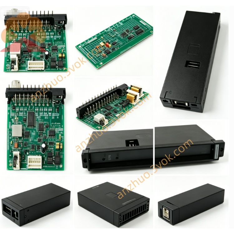
NI PXI‑2567 64‑Channel External Relay Driver Module
Description
II. Model Interpretation
PXI: Compliant with the PXI bus specification, compatible with PXI mixed slots and PXIe mixed slots
2567: The serial number of the NI universal relay module series, representing a 32-channel SPST small current universal relay
Full name: PXI-2567 32-Channel SPST PXI Relay Module
Topology Identifier: NISWITCH_TOPOLOGY_2567_32_SPST, topology fixed, cannot be reconfigured by software
III. Technical Parameters
Switch Electrical Characteristics
Topology Structure: 32 independent SPST (Form A, normally open), each path includes a common terminal COM and a normally open terminal NO
Relay Type: Electromechanical non-latching relay, gold-plated contacts
Maximum Switching Voltage: 150 VDC / 125 VAC (CAT I)
Maximum Switching / Carrying Current: 2 A per channel
Maximum Switching Power: 60 W (DC), 62.5 VA (AC, industrial frequency)
On-State Resistance: Typical value < 50 mΩ
Thermal Offset: Typical value < 1 µV
Operating Bandwidth: DC ~ 10 MHz
Action Time: Typical 2 ms, maximum 4.4 ms
Isolation Strength: Channel-to-channel, channel-to-ground withstand voltage 150 Vrms
Life and Scan Parameters
Mechanical Life: 2×10⁷ times
Full Load Electrical Life: 1×10⁵ times
Scan List: Maximum support 1024-step programmable scan sequence
Full Channel Scan Rate: Maximum 115 times/second
Trigger and Control
Trigger Interface: Supports hardware triggering of PXI backplane Trigger 0~7
Minimum Trigger Pulse Width: 150 ns
Board-Integrated Functions: Each relay channel is independently counted for life monitoring
Physical and Environmental Parameters
Form Specification: Standard 3U PXI single-slot module
Connector: Front panel 78-pin D-SUB female connector
Overall Size: 216 mm × 20 mm × 130 mm
Weight: Approximately 0.3 kg
Power Supply: PXI backplane 5 V power supply, typical power consumption 4.8 W
Operating Temperature: 0 ℃ ~ 55 ℃
Storage Temperature: -20 ℃ ~ 70 ℃
Relative Humidity: 5% ~ 85%, no condensation
IV. Interface and Communication Configuration
Front-End I/O Interface
The 78-pin D-SUB connector is the only external signal interface, integrating all 32 SPST channels
Pin Definitions: Include 32 COM common terminals, 32 NO normally open terminals, and the remaining pins are shielded ground and reference ground
All channels are electrically independent, a failure of a single path does not affect the normal operation of the remaining channels
Bus and Software Communication
Bus: Standard PXI backplane bus, automatically acquires power supply, clock and trigger signals, compatible with PXIe chassis mixed slots
Driver: Standard NI-SWITCH, compliant with IVI driver specification
Upper-level Software Support: Mainstream development environments such as LabVIEW, TestStand, LabWindows/CVI, Python, etc.
Basic Configuration Functions: MAX hardware recognition, channel status reading, scan sequence editing, trigger mode configuration, relay count reading
Synchronization Capability: Relying on the PXI backplane trigger bus, can achieve high-precision synchronous switching of multiple modules and multiple instruments
V. Core Functions
Ultra-high Channel Density: A single PXI single-slot integrates 32 independent switches, significantly saving chassis slots, suitable for large-scale multi-channel signal switching. Precise signal adaptation: low on-resistance conduction, low thermal offset, suitable for low-level analog signals, precise voltage and current loop switching, reducing measurement errors.
Stable switching performance: electromechanical relays have fast response speed and support high-frequency scanning, meeting the efficiency requirements of mass production testing.
Hardware synchronous triggering: supports PXI backplane hardware triggering, precise timing of multi-module synchronization, suitable for synchronous acquisition and parallel testing systems.
Relay life monitoring: onboard independent counting function, real-time statistics of on-off times, achieving predictive maintenance, reducing unplanned downtime.
Programmable scanning sequence: built-in 1024-step scanning list, offline presetting of switching logic, hardware automatically executes, enhancing automation level.
Six. Application scenarios
Semiconductor and component testing: chip pins, discrete components, multi-channel signal selection and functional testing of circuit boards.
Industrial data acquisition: signal switching of multiple measurement points sensors, multi-channel multiplexing of analog signals such as temperature humidity / pressure.
Automotive electronic testing: vehicle wiring, on-board sensors, low-voltage control circuits for on-off detection.
Automation ATE production line: small and medium power loads, control signals for program-controlled switching, suitable for batch mass production testing.
Laboratory research: multi-channel signal routing, loop switching, multi-scheme comparison testing.
Measurement and control system integration: building a distributed multi-channel switch array to achieve signal scheduling of large testing systems.
Seven. Usage and Maintenance Instructions
Usage points
Installation: Insert the module into the standard 3U slot of the PXI chassis, tighten the panel screws, ensure reliable backplane contact, and keep away from strong vibration and strong electromagnetic interference areas.
Connection: Use matching 78-pin D-SUB cables, gently insert and remove, avoid violent pulling; for low-voltage signal circuits, priority should be given to using shielded cables, and reliable grounding.
Electrical limits: Strictly follow the 150 V, 2 A usage specifications,严禁 overpressure and overcurrent operation; for inductive loads such as drive coils and electromagnetic coils, external series diodes or surge suppression devices must be connected to prevent reverse high voltage from damaging contacts.
Mode selection: For daily debugging, use software for immediate triggering; for multi-module synchronization and high-speed scanning scenarios, enable PXI hardware triggering.
Power-on specifications: Complete wiring before powering on, disconnect and plug the signal cables after power off, to avoid arc damage to contacts when plugging and unplugging while powered.
Maintenance instructions
Regular inspection: Check every quarter whether the D-SUB connector is loose, oxidized, or dusty, clean the interface in time to ensure good contact.
Life management: Regularly read the number of on-off times of the relay through NI-SWITCH, when the number approaches 1×10⁵ times under load conditions, plan to replace the module in advance.
Environmental control: Maintain a dry and ventilated working environment, avoid condensation and dust accumulation, keep the working temperature within 0~55 ℃.
Fault handling: When there is a channel failure or abnormal signal, first check the wiring and grounding; through the MAX diagnostic switch status, the relay of this module cannot be replaced on-site, hardware faults need to be replaced or sent for repair as a whole.
Storage requirements: When not in use for a long time, disconnect all cables, protect the interface with dust-proof measures, place it in a dry environment of - 20~70 ℃, away from high temperatures, corrosion, and strong magnetic fields areas.
Calibration: It is recommended to conduct a full calibration once a year, check the on-off status, conduction resistance, etc., to ensure test accuracy.
Get a Quote