
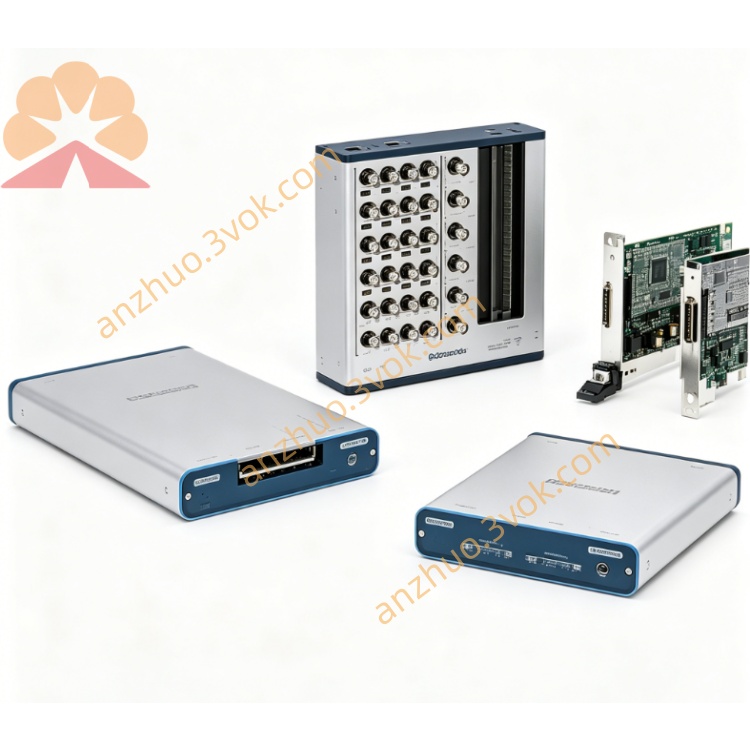
NI PXI‑2722 5‑Channel 16‑Bit Programmable Resistor Module
Description
II. Model Interpretation
PXI: Standard PXI bus, compatible with PXI/PXIe hybrid slots.
2722: NI programmable resistor series code, representing 16-bit, 5-channel, 0.25Ω to 16320Ω high-precision resistor module.
Full name: PXI-2722 16-bit 5-channel programmable resistor module.
Topology: 16-bit resistor network per channel (2¹⁶ = 65536 steps), 0.25Ω step, independent channel control.
III. Technical Parameters
(1) Core Characteristics of Resistors
Number of channels: 5 independent channels
Resolution: 16 bits (0.25Ω step)
Resistor range: 0.25Ω to 16320Ω (per channel)
Base accuracy: ±0.5% (23℃)
Temperature coefficient (TCR): 100 ppm/℃
Typical channel accuracy:
20Ω to 40Ω: <10.0%
40Ω to 16320Ω: <2.0%
(2) Electrical Rated Values
Maximum voltage between channels: 60 VDC / 30 VAC (peak)
Maximum current per channel: 0.3 A
Maximum power per channel: 0.25 W
(3) Switches and Relays
Relay type: Reed Relay
Action/Release time: Typical 250 μs
Upper limit of simultaneous drive: 89 relays
Mechanical life: 1×10⁷ times (1 V/10 mA)
(4) Physical and Environmental
Form: Standard 3U PXI single-slot module
Front-end connector: 37-pin D-SUB (male) + 2×2 Micro-Fit (DMM sensing)
Size: 216 mm × 20 mm × 130 mm
Weight: Approximately 0.27 kg
Power supply: 3.3 V/1.2 W; 5 V / maximum 11 W
Operating temperature: 0 ℃ to 55 ℃
Storage temperature: -20 ℃ to 70 ℃
Humidity: 5% to 85%, no condensation
IV. Interface and Communication Configuration
(1) Front-end I/O Interface
37-pin D-SUB (male): 5 differential channels (CHx+/CHx‑), bus positive/negative (Bx+/Bx‑), DMM sensing (HI/LO, HI SENSE/LO SENSE).
2×2 Micro-Fit: Assists in DMM connection, supports 4-wire Kelvin measurement, eliminating lead resistance errors.
(II) Bus and Software Communication
Bus Interface: PXI backplane, supports PXIe mixed slots / PXI peripheral slots.
Driver: NI-SWITCH, compliant with IVI standards.
Software Support: LabVIEW, TestStand, LabWindows/CVI, Python, C, .NET.
Basic Functions: NI MAX can hardware recognize, channel resistance configuration, relay status monitoring, life counting.
Trigger Capability: Supports PXI backplane Trigger 0-7, used for multi-module synchronous switching.
VII. Core Functions
5-channel 16-bit high-resolution resistance: 0.25Ω step, range up to 16.32 kΩ, accurately simulates RTD, potentiometer, strain bridge, etc. precise resistance signals.
Wide range + high precision: covers low resistance to high resistance, above 64Ω with precision better than 2%, meeting calibration-level testing requirements.
4-wire Kelvin measurement: dedicated sensing interface, eliminates cable resistance influence, improves measurement accuracy.
HIL High Resistance Environment Simulation: simulates high resistance changes of sensors such as temperature, displacement, pressure, etc., for ECU / controller closed-loop testing.
Relay Life Monitoring: onboard counter records on/off times, supports predictive maintenance, reduces downtime risks.
Compact Single Slot Design: 3U PXI single slot integrates 5 channels, saves cabinet space, suitable for high-density testing.
VIII. Application Scenarios
High Precision RTD / Thermocouple Calibration: simulates RTD wide range resistance values such as PT100/PT1000, used for precise calibration of temperature measurement systems.
High Resistance Sensor Simulation: simulates high resistance sensors such as pressure, displacement, humidity, etc., to verify the linearity and sensitivity of the acquisition system.
Hardware-in-the-Loop (HIL) Testing: simulation of high resistance sensor signals for automotive ECU, industrial controllers, avionics equipment.
Precise Voltage Division / Bridge Test: simulates high precision potentiometers, strain bridge resistance changes, tests circuit response and accuracy.
Automated Production Testing: batch testing of precise resistance sensors, instruments, controllers' input impedance and signal acquisition accuracy.
IX. Installation and Maintenance Instructions
(1) Installation and Power On
Install on PXIe mixed slot or PXI peripheral slot. Do not use pure PXIe slot.
Before installation, power off, fully insert the module and tighten the panel screws.
After powering on, confirm device identification is normal and there are no errors in NI MAX.
(2) Connection and Operation
Use 37-pin D-SUB cable, differential connection (CHx+/CHx‑), avoid common ground interference.
For high-precision measurement, enable 4-wire Kelvin mode, connect HI/LO and Sense lines, eliminate lead resistance.
Each channel current ≤ 0.3 A, power ≤ 0.25 W, prevent relay contacts from burning out.
Programming Control: Set channel resistance, configure scan sequence and trigger through NI-SWITCH API.
(3) Maintenance and Lifespan
Regularly read relay on/off times in NI MAX, replace when approaching 1×10⁷ times.
Maintain ventilation and cooling, working temperature ≤ 55 ℃, avoid accelerating aging due to high temperature.
Avoid overpressure, overcurrent operations, prevent contact oxidation or adhesion.
When not in use for a long time, store in a dry environment (-20 ℃ to 70 ℃), avoid oxidation of contacts due to moisture.
Get a Quote