
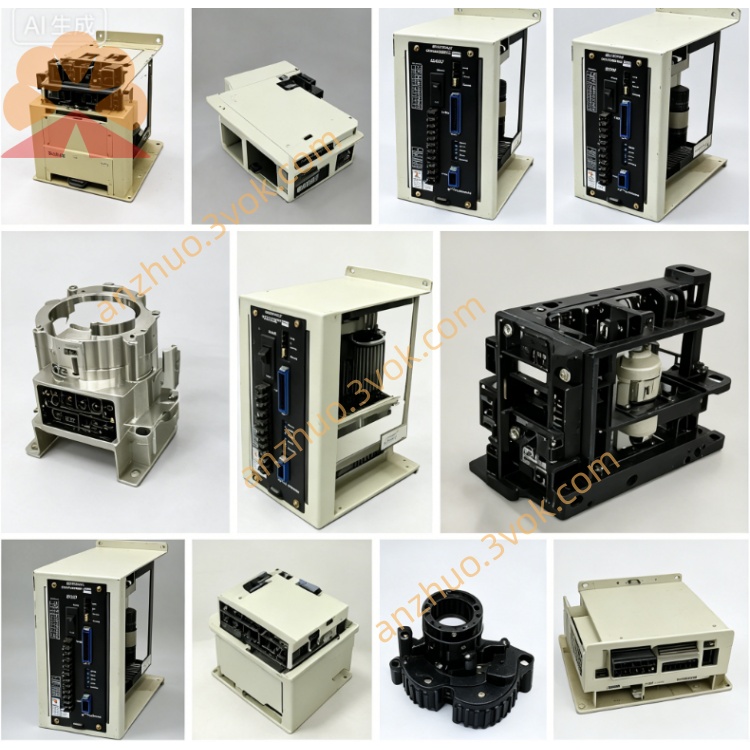
JANCD-GCP01
Description
Technical Specifications
The system bus supplies power uniformly, and internal multi-channel voltage conversion outputs are provided to meet the regular power consumption requirements of the board cards. The circuit has overvoltage, undervoltage, and short-circuit protection mechanisms, effectively avoiding damage to components due to abnormal voltages. The board card integrates multiple power supply output ports to meet the power specifications of different functional board cards. The operating temperature range is 0 to 55 degrees Celsius, the storage tolerance temperature range is wide, the working environment is kept dry without condensation, and the structure conforms to the standard cabinet slot installation dimensions. It has industrial environment anti-interference performance.
Installation and Wiring
The board card is vertically installed in the corresponding slot position of the control cabinet, with a reserved ventilation and heat dissipation area around it. The fastening and fixing components are tightened to avoid displacement and poor contact due to vibration during operation. The metal casing is reliably connected to the grounding end of the cabinet to reduce electromagnetic interference. The internal circuit relies on the backplane bus to complete power supply intercommunication, and only the system main power supply line is connected externally. The wiring is connected according to the board surface markings, and the cables are selected in the appropriate specifications. The strong and weak electrical lines are arranged separately for wiring, maintaining a reasonable distance to reduce mutual influence of the lines.
Maintenance and Care
Daily check the appearance of the board surface components, observe the operation status of the power supply indicator light, and check for any abnormal conditions such as overheating, component deformation, etc. Regularly use a dry low-pressure gas source to clean the board surface and dust accumulated in the slots to ensure good heat dissipation and circuit contact. Regularly check the tightness of the connection terminals and plug-in ports, check for any aging hazards of capacitors and circuit solder joints, and simultaneously verify the reliability of the grounding connection. When the equipment is in a long-term static and stopped state, it should be stored without power supply, and dust and moisture protection should be done. Before reactivation, conduct a no-load power-on test to check the power supply condition.
Fault Diagnosis
The power supply indicator light fails to light up, mostly due to the interruption of main line power supply, board card fuse element damage, or voltage conversion chip failure. The incoming line voltage and internal circuit are used to determine the fault location. Frequent power-off and restart of system modules usually indicate unstable voltage output, loose wiring, or overload of the load. Review the output circuit to identify abnormal loads. When some functional modules of the entire machine cannot start, the corresponding branch power supply circuit is abnormal. Sequentially detect the output voltage to identify damaged components. When there is a circuit error alarm during operation, it is mostly due to short circuits in the lines or protection elements triggering protection. Power-off and check the line conductivity status. For the same specification board cards, they can be directly replaced and used. After assembly, conduct a no-load power-on test to verify the stability of the power supply.
Get a Quote