
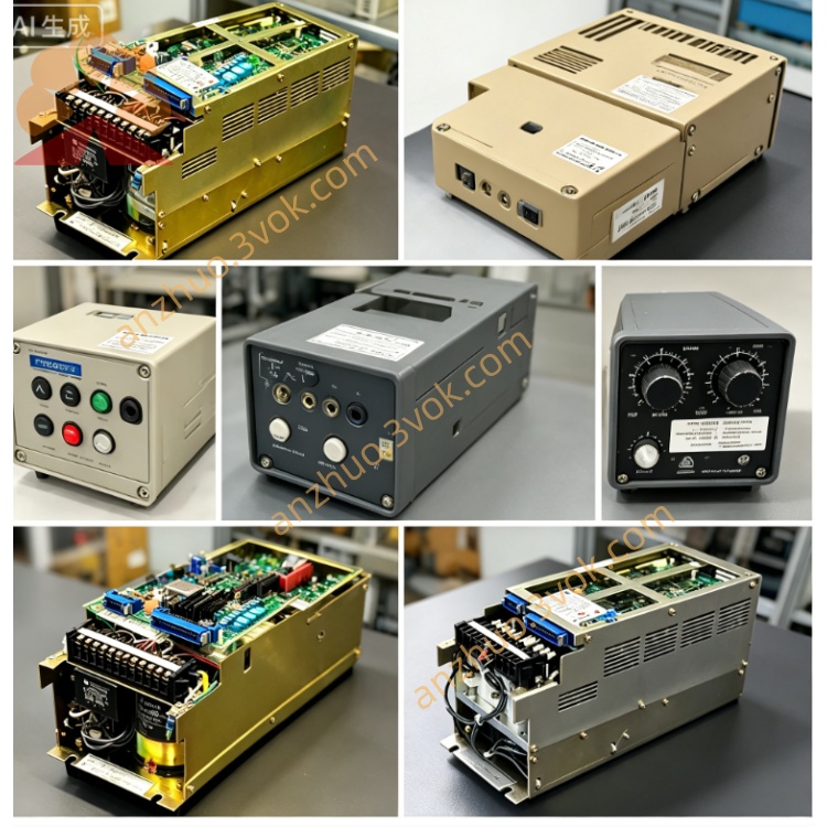
JANCD-G1R01
Description
Technical Specifications
Power Supply: Backplane bus, DC24V ±10%, power consumption approximately 18W
Communication Interface: Built-in remote I/O bus, RS-232/422/485, I/O expansion interface
I/O Capacity: Supports expansion of up to 64 input points / 64 output points (remote module)
Transmission Distance: Maximum 200m for remote bus (twisted-pair shielded wire)
Environment: Operating temperature 0–55℃, storage temperature -20–70℃, humidity 10%–90% (no condensation)
Structure: 3U standard board card, metal shielding enclosure, weight approximately 0.5kg
Installation and Wiring
Vertically installed in the 3U vacant slot of the control cabinet, leaving ≥50mm space for heat dissipation on top and bottom, and locking with screws to prevent vibration. The metal enclosure is reliably connected to the cabinet ground (ground resistance ≤ 4Ω).
Internal: Power supply and system communication are automatically completed by the backplane bus, without internal strong current wiring.
External: Only connect remote I/O modules, communication serial ports, external I/O terminals, etc. for low-voltage signals; single-ended grounding of the shielded wire, separation of strong and weak current wiring, spacing ≥ 10cm; remote bus uses dedicated twisted-pair wire, connector firmly pressed.
Maintenance and Care
Daily observation of the power supply, communication, and fault indicator light status of the board; no bulging, burning, or peculiar smell on the board surface.
Quarterly: Use low-pressure dry compressed air to blow dust from the board and slots, maintaining good heat dissipation.
Every six months: Check the tightness of all plugs, terminals, capacitors, and solder joints, no aging or leakage of liquids; retest the continuity of grounding.
Long-term shutdown: Cut off the power supply, take precautions against dust and moisture; preheat for 30 minutes with no external equipment connected before restarting.
Fault Troubleshooting
No power indicator: Backplane DC24V power supply abnormal, board card fuse blown, power chip damaged; measure the bus voltage, check the fuse, replace the board card for testing.
Communication interruption (light does not flash): Bus interface loose, communication chip failure, remote module power-off; reinsert the plug, measure the interface signal, and troubleshoot the remote power supply.
No response from I/O signals: I/O terminal loose, optocoupler damaged, remote module failure; check the wiring, measure the signal level, and replace the module.
Data packet loss / error code: Poor shielding, interference from strong and weak current, unstable grounding; optimize wiring, reinforce grounding, replace the shielded wire.
Random error and system crash: Virtual soldering of chips, oxidation of slots, excessive interference; clean the slot, reinsert and pull out, replace the board card for verification.
Get a Quote