
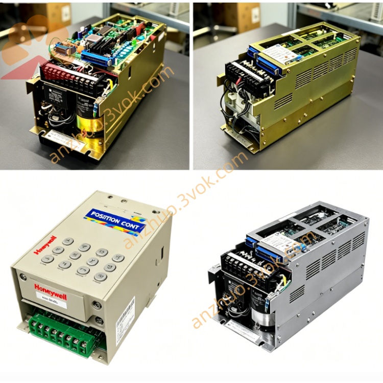
JANCD-G10
Description
JANCD-G10
Product Overview
JANCD-G10 is an I/O interface board for YASNAC 2000G and 3000G series CNC systems from ABB. The material numbers are DF7000063 and DF8000006. It mainly realizes signal transfer and isolation between the CNC system and external equipment of the machine tool, connects operation panels, sensors, relays and various actuators, and completes the interaction of control instructions issuance and equipment status feedback. It adopts a plug-in type board structure, relying on the backplane bus of the cabinet for data and power transmission. It can be combined with graphics boards, axis control boards and power supply boards of the same series to form a complete control system, and is suitable for use in various CNC machining machines.
Technical Specifications
In the bus power supply mode, the working voltage is DC24V, with a voltage fluctuation range of plus or minus 10%. The operating power consumption is 15W. It has 32 signal input terminals, which are adapted to DC24V voltage. It is compatible with dry contacts and PNP signal types, and the signal response is rapid. It is equipped with 32 transistor output terminals, with a maximum output current of 0.5A per channel. It comes with overcurrent and short circuit protection, and can automatically recover after a fault.
The operating environment temperature range is 0 degrees Celsius to 55 degrees Celsius. The storage temperature range is from minus 20 degrees Celsius to 70 degrees Celsius. The operating environment humidity should be kept without condensation. The overall structure is compatible with the standard slots of the control cabinet, and it has industrial anti-vibration capabilities. The electrical operation stability is strong.
Installation and Wiring
The board card is vertically assembled inside the control cabinet slot. Adequate heat dissipation space is reserved during assembly. Installation fasteners are fixed and locked to avoid vibration-induced contact offset. The metal shell of the board card is firmly connected to the grounding terminal of the cabinet to weaken the electromagnetic interference.
The equipment is equipped with two sets of external signal interfaces. Internal communication is completed through the backplane bus. The input interface collects all signal terminals and the common power supply terminal, while the output interface integrates the output terminals and the zero potential common terminal.
The wiring is laid according to the signal type specifications. External sensors and switch components are connected to the input terminals, and the load equipment is connected to the output terminals. Appropriate specification cables are selected for wiring, and long-distance signal lines use shielded cables and are single-ended grounded. The power and weak current lines are arranged separately to maintain a safe distance and avoid mutual interference of the lines, causing abnormal signals.
Maintenance and Care
During daily inspections, check the appearance of the board. Pay attention to any invisible deformation or burning marks on the board components, and observe the working status of the operation indicator lights. Regularly use a low-pressure dry air source to clean the board surface and slot dust accumulation to ensure smooth heat dissipation.
Regularly tighten the wiring terminals and connection plugs to check for oxidation and loosening of the lines. Check the appearance of the capacitor components on the board card and promptly check for leakage, bulging, and other aging problems. Simultaneously verify the reliability of the grounding connection.
During long-term static storage and shutdown, keep the equipment powered off and stored. Take measures to prevent moisture and dust. Before restarting and using, perform no-load power-on preheating to confirm normal operation conditions before putting it into use.
Troubleshooting
If the power indicator light does not light up, it is usually caused by abnormal bus power supply, damage to the board card fuse and power chip. Check the power supply voltage and replace the components to verify the fault location.
If the operation indicator light works abnormally, there are usually problems such as abnormal bus communication, hardware program abnormalities, or insufficient board card compatibility. Re-stabilize the board card connection and check the hardware compatibility specifications to solve the problem.
If the input signal cannot be triggered, it is usually due to the absence of external power supply, wiring deviation, or damage to the input component. Check the power supply circuit, short-circuit the terminals to distinguish between line and body faults.
If the output indicator is normal but the load does not act, it is likely that the output component is damaged, there is a short circuit in the rear load, or the wiring is loose. Power off and test the line resistance to check the load operation conditions.
During operation, if there is signal disorder and false triggering, it is usually caused by inaccurate grounding, interference from line layout, etc. Optimize the grounding structure and re-arrange the strong and weak current wiring to improve the situation.
For the same specification board cards, they can be directly replaced and used. After replacement, perform a no-load trial run to confirm the stability of signal transmission and the overall machine operation.
Troubleshooting
If the power indicator light does not light up, it is usually caused by abnormal bus power supply, damage to the board card fuse and power chip. Check the power supply voltage and replace the components to verify the fault location.
If the operation indicator light works abnormally, there are usually problems such as abnormal bus communication, hardware program abnormalities, or insufficient board card compatibility. Re-stabilize the board card connection and check the hardware compatibility specifications to solve the problem.
If the input signal cannot be triggered, it is usually due to the absence of external power supply, wiring deviation, or damage to the input component. Check the power supply circuit, short-circuit the terminals to distinguish between line and body faults.
If the output indicator is normal but the load does not act, it is likely that the output component is damaged, there is a short circuit in the rear load, or the wiring is loose. Power off and test the line resistance to check the load operation conditions.
Get a Quote