170XTS04000
Description
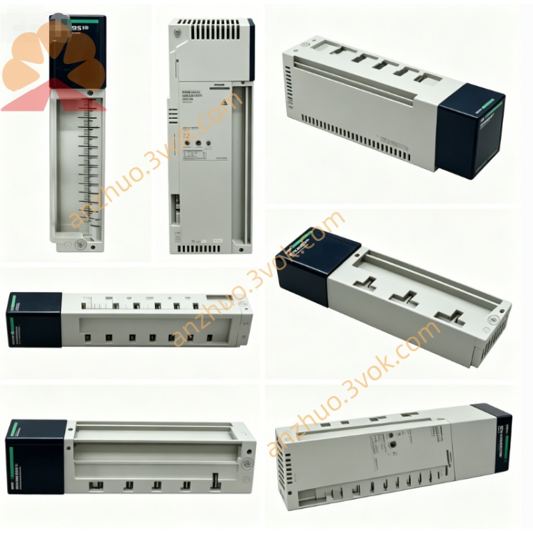
1. General Description
2. Product Identification
Model: 170XTS04000
Manufacturer: Schneider Electric
Series: Modicon Momentum / Quantum / Premium / M221/M241/M251
Type: RS485 / Modbus Plus T‑connector (DB9 ↔ RJ45×2)
Ports: 1×DB9 female, 2×RJ45 (8P8C, shielded)
Function: Network branching, line splitting, DB9–RJ45 conversion
Cable Compatibility: Modbus Plus/RS485 shielded twisted pair
Protection Class: IP20 (mated)
Material: UL94 V‑0 flame retardant housing, metal shielded shell
Certifications: CE, UL, CSA, RoHS
Weight: Approx. 0.19 kg
Status: Discontinued (replaced by equivalent adapters)
3. Technical Specifications
Electrical
Protocol: Modbus Plus, RS485 (half‑duplex)
Data Rate: Up to 1 Mbps (Modbus Plus)
Contact Rating: 1 A, 50 VDC
Insulation Resistance: ≥ 500 MΩ
Contact Resistance: ≤ 20 mΩ
Shielding: 360° metal shield, continuous ground path
Mechanical
Insertion Cycles: ≥ 750 (RJ45), ≥ 500 (DB9)
Cable Diameter: 5–8 mm (RJ45 side)
Wire Gauge: 24–26 AWG (twisted pair)
Mounting: Free‑standing or DIN rail (optional clip)
Environmental
Operating Temperature: 0 °C to +60 °C
Storage Temperature: −40 °C to +85 °C
Relative Humidity: 5%–80%, non‑condensing
Vibration: 5 g RMS (IEC 60068‑2‑6)
4. Pinout (DB9 ↔ RJ45)
Modbus Plus / RS485
- DB9 Female (Pin → Signal):
1: Data− (B)
2: Data+ (A)
3: GND
4–6: Not used
7: Shield (GND)
8–9: Not used
- RJ45 (8P8C) (Pin → Signal):
1–2: Data+ (A)
3–6: Data− (B)
4–5: GND
7–8: Shield (GND)
5. Key Features
T‑junction function: Splits one DB9 line into two RJ45 lines (or vice versa)
Dual‑protocol support: Works with Modbus Plus and standard RS485
Fully shielded: Reduces EMI/RFI in industrial environments
Legacy compatibility: Connects DB9‑equipped PLCs to modern RJ45 cabling
Plug‑and‑play: No configuration required
Robust industrial design: For factory floor installation
6. Applications
Connecting Modicon Quantum/Momentum PLCs (DB9) to RJ45 Modbus Plus networks
Creating branch points in RS485/Modbus Plus daisy‑chain topologies
Interfacing legacy DB9 devices with new RJ45 field cables (170XTS02200)
Networking HMIs, I/O modules, and drives in high‑noise industrial areas
7. Installation Steps
Power off the entire communication network before installation.
Mount the 170XTS04000 in a clean, dry location (DIN rail or free‑standing).
Connect the DB9 female port to the PLC/device DB9 male connector.
Connect RJ45 Port 1 to the main network cable (from previous node).
Connect RJ45 Port 2 to the next node or branch cable.
Ensure all shields are properly connected (DB9 pin 7, RJ45 pins 7–8).
Verify continuity and shield integrity with a multimeter.
Power on the network and test communication.
8. Maintenance
Inspect ports periodically for dirt, corrosion, or bent pins.
Check shield connections for continuity (no loose strands).
Avoid excessive cable bending near the adapter.
Replace if housing is cracked or contacts are damaged.
9. Safety Instructions
Installation must be performed by qualified personnel.
Disconnect all power before wiring or modifying the network.
Do not expose to liquids, corrosive gases, or conductive dust.
Use only with rated voltage and communication protocols.
10. Troubleshooting
No communication:
Check DB9/RJ45 pinout (Data+/Data− alignment).
Verify shield connection (DB9 pin 7, RJ45 7–8).
Reseat connectors; check for bent pins.
Intermittent errors:
Ensure all connections are tight and shields are continuous.
Reduce nearby EMI sources (motors, drives).
Confirm cable length adheres to Modbus Plus limits.
Get a Quote