170XTS02300
Description
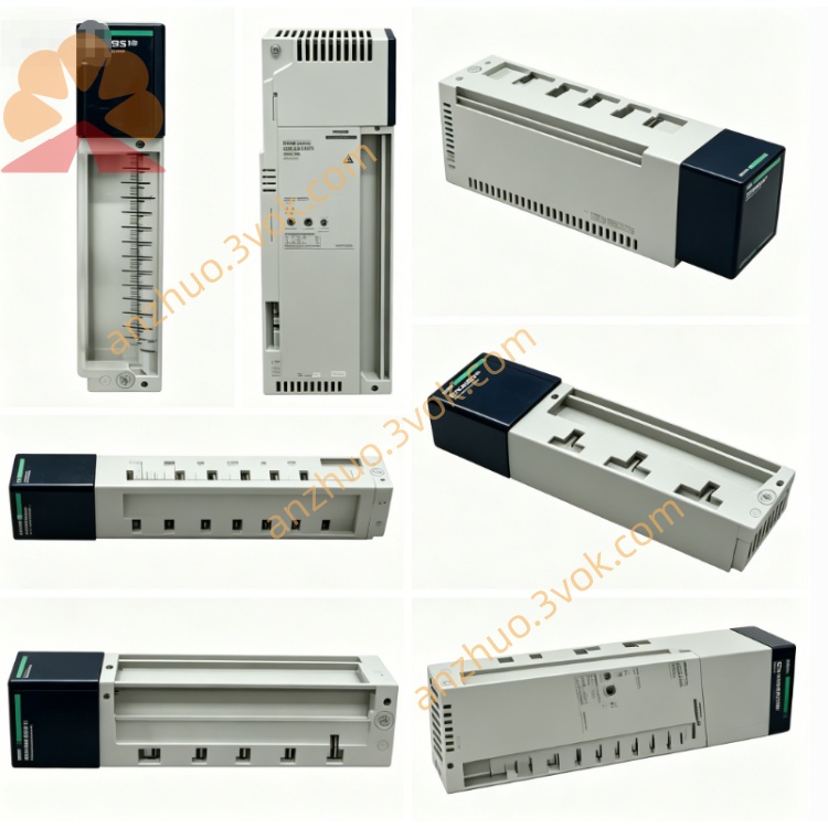
1. General Description
2. Product Identification
Model: 170XTS02300
Manufacturer: Schneider Electric
Series: Modicon Momentum / Quantum / Premium
Type: Shield Earthing Clamp Module
Function: Cable shield grounding, EMC/ESD protection
Compatibility: 170XTS02000 (T-connector), 170XTS02100 (terminator), 170XTS02200 (RJ45 connectors)
Mounting: DIN rail or panel mount
Protection Class: IP20
Material: UL94 V-0 flame retardant housing, tinned copper contacts
Certifications: CE, UL, CSA, RoHS
Weight: Approx. 0.15 kg
3. Technical Specifications
Electrical
Grounding Resistance: ≤ 5 mΩ (shield to earth)
Current Rating: 5 A continuous (surge 20 A)
Voltage Rating: 60 VDC max
Insulation Resistance: ≥ 500 MΩ
Mechanical
Clamp Range: 4–10 mm cable diameter
Conductor Size: 24–16 AWG (shield strands)
Insertion Cycles: ≥ 500
Torque Specification: 0.5–0.8 Nm (screw terminal)
Environmental
Operating Temperature: -10 °C to +55 °C
Storage Temperature: -25 °C to +70 °C
Relative Humidity: 5%–95%, non-condensing
Vibration: 5 g RMS (IEC 60068-2-6)
Shock: 50 g peak
4. Key Features
Low-resistance shield grounding: Eliminates floating shields, reduces EMI/RFI interference
Robust clamp design: Securely grips cable shields without damaging conductors
DIN rail/panel mount: Flexible installation in control cabinets
EMC compliance: Ensures Modbus Plus networks meet industrial noise immunity standards
Plug-and-play: No configuration required; installs in seconds
5. Applications
Grounding shields of Modbus Plus/RS485 cables at T-connectors (170XTS02000)
Shield termination at network ends (with 170XTS02100 terminators)
ESD protection for communication lines in high-noise industrial environments
Compatible with Modicon PLCs, I/O modules, and HMIs in Momentum/Quantum/Premium systems
6. Installation Steps
Power off the entire Modbus Plus network before installation.
Mount the 170XTS02300 on a DIN rail or panel near the T-connector/terminator.
Prepare the communication cable: Strip 3 cm of outer jacket, expose shield (do not trim strands).
Open the earthing clamp: Loosen the screw, lift the top plate.
Insert the cable shield into the clamp: Ensure full contact between shield strands and tinned copper plate.
Tighten the screw to 0.5–0.8 Nm (do not over-tighten).
Connect the cable’s RJ45 plug to the T-connector/terminator.
Run a ground wire from the 170XTS02300’s earth terminal to the cabinet’s protective earth (PE) bus.
Verify continuity with a multimeter (shield to PE resistance ≤ 5 mΩ).
7. Maintenance
Inspect the clamp periodically for loose screws, corrosion, or damaged contacts.
Ensure shield strands remain securely gripped (no fraying or breakage).
Check the PE connection for tightness and corrosion.
Keep the housing clean and dry; avoid conductive dust buildup.
Replace the unit if the housing is cracked or contacts are damaged.
8. Safety Instructions
Installation and service must be performed by qualified electricians.
Disconnect all power before wiring or modifying the network.
Ensure the cabinet’s PE bus is properly grounded per local electrical codes.
Do not use beyond rated voltage, current, or temperature limits.
Avoid exposure to liquids, corrosive gases, or explosive atmospheres.
9. Troubleshooting
High noise / intermittent communication errors:
Check shield grounding (ensure 170XTS02300 is properly connected to PE).
Verify clamp screw torque (0.5–0.8 Nm).
Inspect shield strands for breaks or poor contact.
ESD events / system resets:
Confirm all cable shields are grounded at both ends (where required).
Check for floating shields (no ground connection).
Ensure the earthing clamp is mounted close to the T-connector/terminator.
Get a Quote