170ADM54080
Description
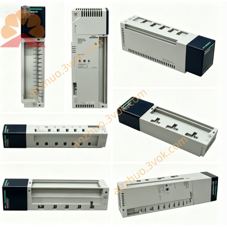
1. General Description
2. Product Identification
Model Number: 170ADM54080
Series: Modicon Momentum
Type: Modbus MCC discrete I/O base (AC)
Channel Configuration:
6 inputs (120 VAC, 47–63 Hz, positive logic)
3 outputs (120 VAC, solid‑state, sourcing)
Dimensions (W × D × H): 125 × 47.5 × 141.5 mm
Weight: 0.24 kg
Protection Class: IP20
Certifications: CE, UL, cUL, CSA, RoHS, Green Premium
Communication: Modbus RTU (8‑bit) / ASCII (7‑bit), 0–247 addresses
Logic Type: Positive (true high)
3. Electrical Specifications
Inputs (6 Channels, 120 VAC)
Rated Voltage: 120 VAC (0–132 VAC range, 47–63 Hz)
Logic 0 (Low): ≤ 40 VAC
Logic 1 (High): ≥ 74 VAC
Input Current (High): ≥ 5.5 mA
Surge Current: 30 mA (rated)
Response Time:
0 → 1: ≤ 12.5 ms @ 60 Hz
1 → 0: ≤ 12.3 ms @ 60 Hz
Overvoltage Protection: 200 VAC (transient)
Outputs (3 Channels, Solid‑State, 120 VAC)
Rated Voltage: 120 VAC (47–63 Hz, ≤ 132 VAC max)
Output Type: Sourcing solid‑state switch
Current per Point: 0.5 A (continuous)
Current per Module: 1.5 A (max)
Leakage Current (Off): < 1.9 mA @ 120 VAC
Voltage Drop (On): < 1.5 V @ 0.5 A
Response Time:
0 → 1: ≤ 12.5 ms @ 60 Hz
1 → 0: ≤ 12.3 ms @ 60 Hz
Protection: Overload, short‑circuit (per channel)
Power & Communication
Supply Voltage: 120 VAC ±10% (108–132 VAC, 47–63 Hz)
Current Consumption: 125 mA @ 120 VAC
Power Dissipation: ≤ 15 W (max)
Modbus Interface: RS‑485, 9.6–115.2 kbps
Port Timeout: 150 ms
Isolation (Field ↔ Bus): 500 VAC
4. Environmental Ratings
Operating Temperature: 0 °C to +60 °C (non‑condensing)
Storage Temperature: −40 °C to +85 °C (non‑condensing)
Relative Humidity: 5% to 95% (non‑condensing)
Vibration: IEC 60068‑2‑6 (1 g, 10–150 Hz)
Altitude: Up to 5000 m (derate above 2000 m)
EMC: IEC 61000‑6‑2, IEC 61000‑6‑4
5. Key Features
9 LED Indicators: 6 for input status, 3 for output status, plus Modbus activity LED
Modbus Communication: Onboard RS‑485 for direct connection to Modbus networks
120 VAC Native I/O: Eliminates need for AC/DC converters in MCC panels
Removable Terminal Blocks: Simplifies wiring and maintenance
Snap‑On Mounting: Quick attachment to Momentum backplane
Per‑Channel Protection: Overload/short‑circuit protection with LED fault indication
2/4‑Wire Wiring: Supports both 2‑wire and 4‑wire field device connections
6. Compatibility
Backplane: Modicon Momentum I/O base rack
Adapters: 170ENT (Ethernet), 170PBM (Profibus), 170CPS (power supply) series
PLC Compatibility: Quantum, Premium, M340, Momentum controllers
Modbus Masters: Any Modbus RTU/ASCII master (PLC, HMI, SCADA)
7. Applications
MCC Panels: Monitoring and control of 120 VAC motor control devices
Industrial Automation: 120 VAC sensors, limit switches, and pushbuttons
Motor Control: 120 VAC contactors, relays, and motor starters
Building Automation: 120 VAC lighting, HVAC, and fan control
Modbus Networks: Distributed I/O for Modbus‑based SCADA systems
8. Installation & Wiring
Power Off: Disconnect all system power before installation.
Mounting: Snap module firmly onto Momentum backplane; ensure proper grounding.
Wiring (Inputs – 120 VAC):
Connect 120 VAC line to input terminal; neutral to common (COM) terminal.
Wiring (Outputs – 120 VAC):
Connect load between output terminal and neutral; 120 VAC line to common (COM).
For inductive loads: Install external RC snubber to suppress voltage spikes.
Modbus Wiring:
Connect RS‑485 (+/−) to Modbus network; use 120 Ω termination resistor at bus ends.
Torque: Tighten terminals to 0.5–0.6 N·m (14–22 AWG copper wire).
Verification: Check connections; power on and confirm LED status and Modbus communication.
9. Maintenance
Periodic Inspection: Check terminal tightness and LED operation every 6 months.
Cleaning: Keep surface free of dust and contaminants; use dry cloth only.
Environment: Avoid corrosive gases, extreme vibration, or moisture.
Modbus Network: Check termination and cable integrity annually.
10. Safety Notes
120 VAC Hazard: Only qualified electricians should perform wiring; follow local electrical codes.
Voltage Limits: Do not exceed 132 VAC on inputs/outputs.
Isolation: Maintain 500 VAC isolation between field and bus circuits.
Inductive Loads: Always use external suppression (RC snubbers) to protect outputs.
Disposal: Dispose of module per local electronic waste regulations.
Get a Quote