170ADM39030
Description
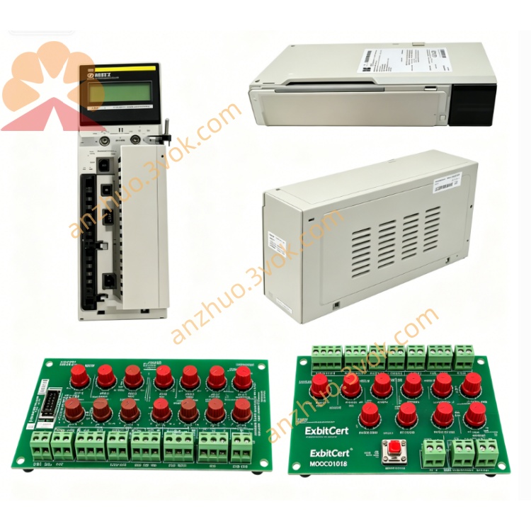
1. General Description
2. Product Identification
Model Number: 170ADM39030
Series: Modicon Momentum
Type: Discrete relay I/O base (DC‑input, AC/DC‑output)
Channel Configuration:
1 group of 10 inputs (24 VDC, sinking)
2 groups of 4 outputs (8 total, relay NO)
Dimensions (W × D × H): 125 × 47.5 × 141.5 mm
Weight: 0.26 kg
Protection Class: IP20
Certifications: CE, UL, cUL, CSA, RoHS, Green Premium
Logic Type: Positive (sink) logic
Input Standard: IEC 61131‑2 Type 1
Isolation: 500 VAC (channels ↔ bus)
3. Electrical Specifications
Inputs (10 Channels, Sinking, 24 VDC)
Rated Voltage: 24 VDC (11–30 VDC operating range)
Logic 0 (Low): −3 VDC to 5 VDC
Logic 1 (High): 11 VDC to 30 VDC
Input Current (High): ≥ 2.5 mA
Input Resistance: 4 kΩ
Response Time:
0 → 1: ≤ 2.2 ms
1 → 0: ≤ 3.3 ms
Outputs (8 Channels, Relay, Form‑A NO)
Load Voltage Range:
DC: 20–115 VDC
AC: 24–230 VAC (50/60 Hz)
Current Rating:
Resistive: 5 A @ 230 VAC / 5 A @ 115 VDC
Inductive: 3 A @ 230 VAC (cos φ ≥ 0.4)
Max Switching Power: 1250 VA (AC) / 575 W (DC)
Min Switching Load: 5 mA @ 24 VDC
Response Time:
Operate (0→1): ≤ 10 ms
Release (1→0): ≤ 10 ms
Mechanical Life: 10,000,000 cycles (no load)
Electrical Life: 100,000 cycles (full resistive load)
Power
Supply Voltage: 24 VDC ±10% (19–30 VDC)
Current Consumption: 120 mA @ 24 VDC (relays off)
Power Dissipation: ≤ 3 W (relays off); ≤ 6 W (all relays on)
4. Environmental Ratings
Operating Temperature: 0 °C to +60 °C
Storage Temperature: −40 °C to +85 °C
Relative Humidity: 5% to 95% (non‑condensing)
Vibration: IEC 60068‑2‑6 (1 g, 10–150 Hz)
Shock: IEC 60068‑2‑27 (15 g, 11 ms)
Altitude: Up to 5000 m (derate above 2000 m)
EMC: IEC 61000‑6‑2, IEC 61000‑6‑4
5. Key Features
18 LED Indicators: 10 for input status, 8 for relay status
Relay Outputs: Isolated Form‑A contacts for AC/DC load flexibility
Wide Voltage Support: Outputs handle 24–230 VAC and 20–115 VDC
Removable Terminal Blocks: Simplify wiring and module replacement
Snap‑On Mounting: Fast attachment to Momentum backplane
Grouped Outputs: 2×4 relays for independent load grouping
Galvanic Isolation: 500 VAC isolation between field and bus circuits
6. Compatibility
Backplane: Modicon Momentum I/O base rack
Adapters: 170ENT (Ethernet), 170PBM (Profibus), 170CPS (power supply) series
PLC Compatibility: Quantum, Premium, M340, Momentum controllers
7. Applications
24 VDC sensors (proximity, photo‑eye, limit switches)
AC/DC actuators: solenoids, contactors, valves, small motors
Building automation: lighting, HVAC, fan control
Process control: pumps, heaters, low‑voltage switchgear
General‑purpose industrial control requiring isolated relay outputs
8. Installation & Wiring
Power Off: Disconnect all system power before installation.
Mounting: Snap module firmly onto Momentum backplane; ensure proper grounding.
Wiring (Inputs – Sinking):
Connect +24 VDC from field device to input terminal; common (COM) to 0 VDC.
Wiring (Outputs – Relay):
Each relay has NO (normally open) and COM terminals.
Connect load between NO and COM; route AC/DC supply to COM.
For inductive loads: Install external RC snubber or flyback diode.
Torque: Tighten terminals to 0.5–0.6 N·m (14–22 AWG copper wire).
Verification: Check connections; power on and confirm LED status.
9. Maintenance
Periodic Inspection: Check terminal tightness and LED operation every 6 months.
Relay Contact Check: For heavy‑use applications, inspect contacts annually for wear.
Cleaning: Keep surface free of dust and contaminants; use dry cloth only.
Environment: Avoid corrosive gases, extreme vibration, or moisture.
10. Safety Notes
Relay Voltage Limits: Do not exceed 230 VAC or 115 VDC on outputs.
Current Ratings: Adhere to 5 A resistive / 3 A inductive limits per relay.
Isolation: Maintain 500 VAC isolation between field and bus circuits.
Qualified Personnel: Only trained electricians should perform wiring; follow local codes.
Disposal: Dispose of module per local electronic waste regulations.
Get a Quote