140XCP40100
Description
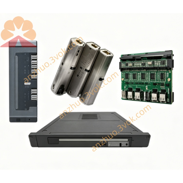
1. Product Description
2. Part Number & Identification
Model: 140XCP40100
Product Line: Modicon Quantum
Type: Front rail / mounting bracket
Size: 19-inch width, 125 mm depth
Weight: 4.97 kg (10.95 lb)
Material: Heavy-duty steel, industrial finish
Country of Origin: France
Certifications: CE, UL, cUL; RoHS compliant
UPC / EAN: 3595861127428
3. Mechanical Specifications
Dimensions (H × W × D):
180 mm × 320 mm × 125 mm
7.09 in × 12.60 in × 4.90 in
Mounting: Front-panel mount (4 × M6 screw holes)
Rack Compatibility: 140XBP01000 Quantum backplane (10-slot)
Shock Resistance: Up to 15G (X, Y, Z axes)
Vibration: Compliant with IEC 60068-2-6 (10–55 Hz)
4. Environmental Ratings
Operating Temperature: 0 °C to +60 °C
Storage Temperature: −40 °C to +85 °C
Humidity: 5 % to 95 % RH, non-condensing
Altitude: Up to 2,000 m (6,562 ft) above sea level
5. Compatibility
Backplanes: Quantum 140XBP series (e.g., 140XBP01000, 140XBP01600)
Cabinets: Standard 19” industrial racks, 125 mm deep enclosures
Application: Fixed installation of Quantum PLC racks in control panels, industrial cabinets
6. Installation Instructions
- Cabinet Preparation
Ensure 19” mounting rails are clean, secure, and properly aligned.
- Bracket Positioning
Place the 140XCP40100 onto the cabinet’s front rails.
Align the four M6 mounting holes.
- Securing the Bracket
Fasten with 4 × M6 screws (torque: 2.5–3.0 N·m).
Verify the bracket is level and rigidly fixed.
- Mounting the Backplane
Slide the Quantum backplane (e.g., 140XBP01000) into the bracket’s guides.
Secure the backplane with captive screws.
- Cable Routing
Route I/O, power, and communication cables with minimum bend radius.
Maintain ≥ 10 cm separation from high-voltage wiring.
7. Maintenance
Inspection: Every 6 months – check for loose fasteners, corrosion, or deformation.
Cleaning: Wipe with a dry cloth; avoid harsh chemicals.
Torque Check: Annually re-torque mounting screws to 2.5–3.0 N·m.
8. Safety Guidelines
Qualified Personnel Only: Installation by trained electricians or panel builders.
De-Energized Installation: Mount bracket and backplane only when system power is OFF.
Load Rating: Do not exceed the bracket’s maximum designed load capacity.
Documentation: Maintain consistent labeling with electrical schematics and as-built drawings.
9. Warranty
12-month manufacturer warranty against defects in materials and workmanship.
Get a Quote