140XBP00600
Description
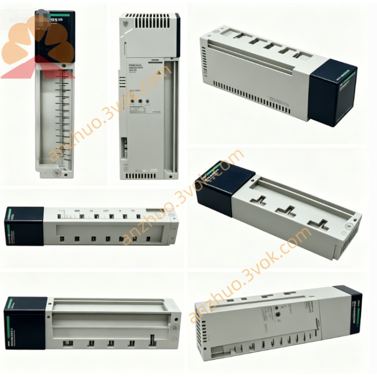
1. Product Overview
2. Key Features
6 module slots: accepts all standard Quantum I/O, CPU, communication, and bus modules.
High‑speed 32‑bit parallel backplane: 100 Mbps bandwidth with low latency.
Integrated power distribution: +5 V for logic and ±12 V for I/O rails to each slot.
Robust metal chassis and fiberglass PCB: provides industrial vibration and noise immunity.
Hot‑swap capable: allows insertion or removal of modules while powered.
Multi‑rack expansion: compatible with 140XBE10000 / 140XBE10000C expanders.
Green Premium: RoHS and REACH compliant.
Certifications: CE, UL, and cUL approved.
3. Technical Specifications
General
Model: 140XBP00600
Type: 6‑slot standard backplane (non‑coated)
Slots: 6 (standard Quantum module form factor)
Bus architecture: 32‑bit high‑speed extension bus
Bus current draw: approximately 1600 mA (from rack PSU)
Power rails: +5 V (logic), ±12 V (I/O)
Weight: approximately 0.64 kg
Mounting: Quantum rack rails or panel‑mount kit
Environmental
Operating temperature: 0 °C to +60 °C
Storage temperature: −40 °C to +85 °C
Humidity: 10–95 % RH, non‑condensing
Altitude: ≤1,000 m (no derating)
Protection class: IP20 (front)
Vibration: 10–150 Hz, 0.15 mm amplitude (IEC 60068‑2‑6)
Shock: 15 g, 11 ms half‑sine (IEC 60068‑2‑27)
Mechanical
Dimensions (W×H×D): 260 × 290 × 104 mm
Material: metal chassis, fiberglass‑reinforced PCB
Connector: high‑density edge connector (module interface)
4. LED Indicators (on Modules, not Backplane)
PWR (Green): module power is OK.
RUN (Green): module is active and backplane communication is normal.
FAULT (Red): module or backplane fault detected.
LINK (Yellow): backplane data activity.
5. Installation & Wiring
Rack Installation
Align 140XBP00600 with Quantum rack rails.
Slide into place and secure with mounting screws (torque to specification).
Insert modules into slots 1–6 until latched.
For multi‑rack systems, connect backplane cables between 140XBP and 140XBE expanders.
Power & Grounding
Power: supplied by the rack PSU; no direct user wiring to the backplane is required.
Ground: connect the chassis to the system earth ground.
Cable routing: separate signal and power cables; use shielded cables in high‑noise areas.
6. Configuration (Unity Pro)
Open Unity Pro V7.0 or later.
In hardware configuration, add a 6‑slot rack and assign 140XBP00600.
Insert I/O modules into slots 1–6.
Configure I/O addresses, diagnostics, and fault handling parameters.
Download the configuration to the CPU; the backplane initializes automatically.
7. Operation & Diagnostics
Normal Operation
All module PWR/RUN LEDs ON, FAULT LEDs OFF.
Backplane provides stable power and communication to all 6 slots.
Fault Conditions
Module FAULT ON: check module seating, connector integrity, or module failure.
No PWR: verify rack PSU operation and backplane voltage rails.
Communication errors: inspect cables, expanders, and system grounding.
Diagnostic Data
Backplane voltage status (+5 V, ±12 V).
Module presence or absence flags.
Bus communication quality metrics.
8. Maintenance
Monthly: inspect module seating, LED status, and cable connections.
Quarterly: check screw torque; clean connectors using compressed air only.
Semi‑annually: verify ground continuity and shield integrity.
Replacement: replace backplane if connectors are damaged or corrosion is present.
9. Safety & Compliance
Qualified personnel only may perform installation, wiring, and maintenance.
Disconnect all power before servicing the system.
For industrial control systems use only; not for direct life‑safety applications without additional safety layers.
Follow local electrical codes and EMC guidelines.
10. Compatibility
Quantum CPUs: 140CPU65150, 140CPU67160, 140CPU68060, 140CPU69060 and newer.
Expanders: 140XBE10000, 140XBE10000C.
I/O modules: all standard Quantum digital, analog, safety, and specialty modules.
Racks: compatible with Quantum 12/14/16‑slot systems.
Get a Quote